Compressed gas operated orbital rolling member vibrator having low noise properties

Active Publication Date: 2005-02-22
VIBCO
View PDF14 Cites 6 Cited by
  • Summary
  • Abstract
  • Description
  • Claims
  • Application Information

AI Technical Summary

Benefits of technology

The present invention may be described with respect to its objects. It is an object of the present inventio

Problems solved by technology

One problem with the known ball vibrators is the high consumption of its operating fluid such as compressed air.
The high consumption of a compressed operating fluid translates into high operating cost due to the consumption of energy such as electricity, fuel and the like that is used for operating an air compressor.
Another problem that has been identified with known ball vibrators is the high noise level that develops after a short period of operation.
This is not acceptable under current noise or sound guidelines.
Many different approaches have been attemp

Method used


Image

  • Compressed gas operated orbital rolling member vibrator having low noise properties
  • Compressed gas operated orbital rolling member vibrator having low noise properties
  • Compressed gas operated orbital rolling member vibrator having low noise properties

Examples


Embodiment Construction

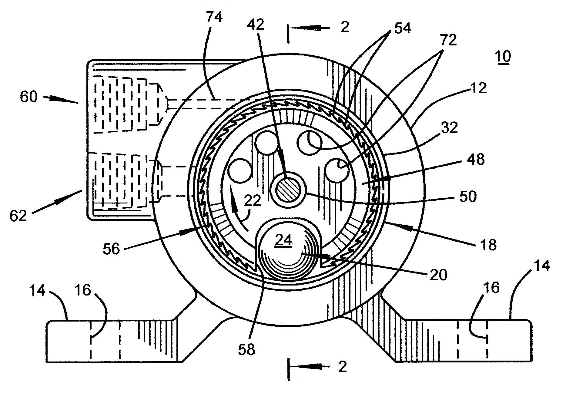
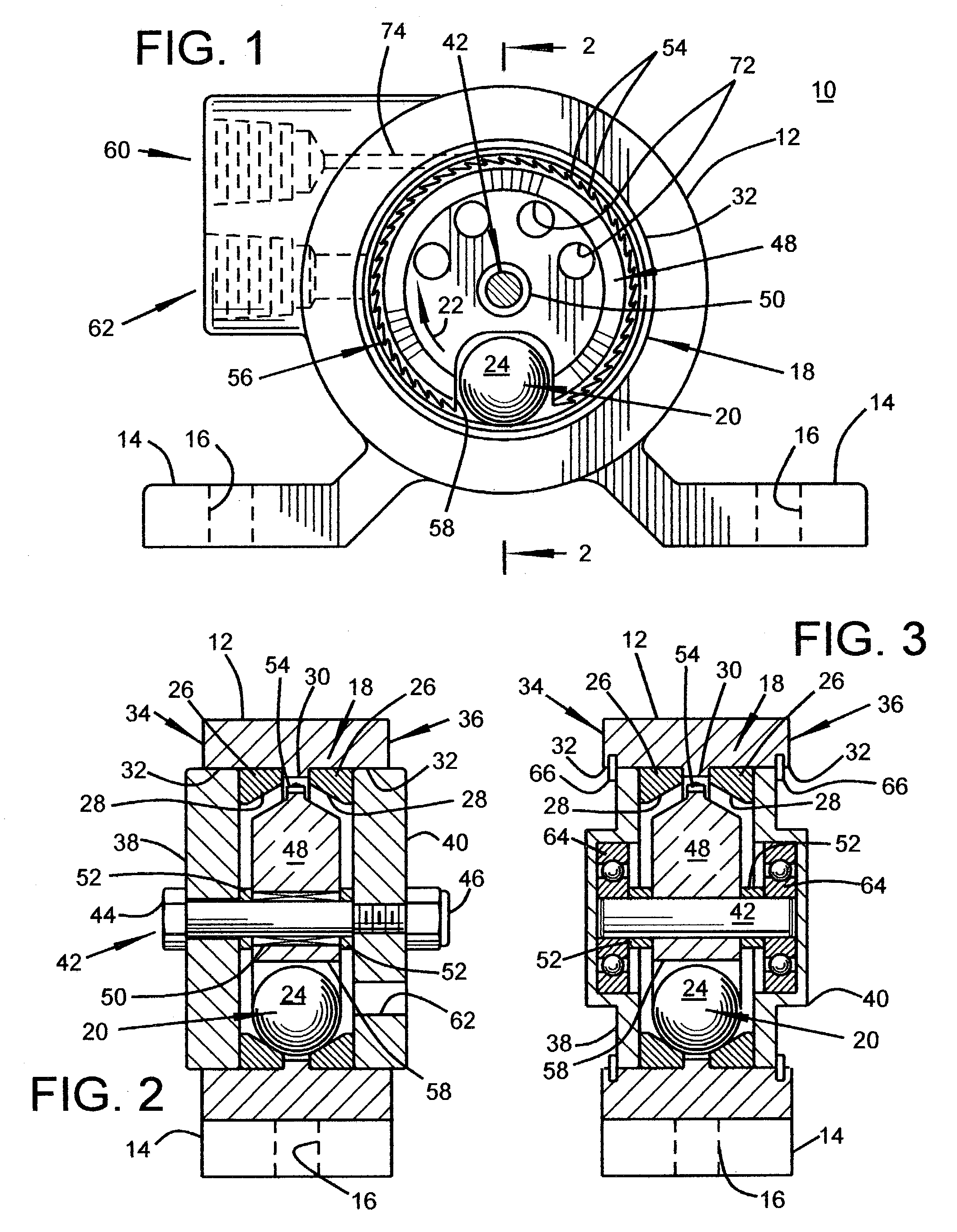
Referring to drawings and first to FIGS. 1 and 2., a ball vibrator assembly of the present invention is generally identified as 10. The ball vibrator assembly 10 includes a generally cylindrical housing 12 that is shown as having a pair of means for mounting or feet 14 that allow the assembly 10 to be removably attached to an item to be vibrated. Threaded fasteners, not shown, are inserted into the through apertures 16 of the feet 14 for the mounting thereof. The cylindrical housing 12 has a raceway 18 formed internally thereof for guiding a rolling member 20 along an orbital path 22. In this first embodiment of the present invention the rolling member is a ball 24. Typically, it is preferred that the raceway 18 be made of a pair of ring members 26 that are removably retained interior of the cylindrical housing 12 as more clearly seen in FIG. 2. Each ring member 26 is formed with a sloping inner diameter 28. The ring members 26 are positioned interior of the housing 12 so that the s...


PUM


Abstract

A compressed air or gas operated vibrator that has a cylindrical housing with a raceway located and formed therein. The raceway is sized and shaped for guiding a rolling member along an orbital path. The vibrator also includes at least one removable end cap for closing any open ends of the housing. The cylindrical housing has an inlet port for directing a flow or jet of the compressed gas to and towards a selected point of the raceway. The vibrator also has an outlet port for exhausting gas from the housing. The vibrator further includes a turbine wheel that rotates inside of the housing with a predetermined clearance. The turbine wheel has a plurality of blade members formed along its outer diameter and a recess portion that is formed into its outer diameter for allowing the rolling member to reside therein while also allowing the rolling thereof. The turbine wheel with the rolling member residing therein rotates interior of the housing by the action of the compressed gas flowing from the inlet port thereby generating an unbalanced vibratory motion with low noise.

Description

CROSS REFERENCE TO RELATED APPLICATION Not Applicable STATEMENT REGARDING FEDERALLY SPONSORED RESEARCH OR DEVELOPMENT Not Applicable BACKGROUND OF THE INVENTION 1. Field of the Invention With regard to the classification of art, this invention is believed to be found in the general class entitled Agitating and more particularly to those subclasses pertaining to vibrators that are operated by a pressurized fluid that acts on an orbital rolling member such as a ball 2. Description of Related Art Orbital rolling element agitating means such as ball vibrators are well known in industry and or commerce for assisting in the discharge of flowable materials from bins, hoppers and the like. This same type of vibrator has also found use in compacting or settling of flowable materials in shipping containers such as; boxes, cartons, crates and the like. Examples of known ball vibrators are U.S. Pat. No. 2,518,250 that issued to Peterson on Aug. 8, 1950 and U.S. Pat. No. 2,917,290 that issued to...

Claims


Application Information

Patent Timeline
IPC IPC(8): B06B1/18
CPCB06B1/186
Inventor WADENSTEN, THEODORE S.
Owner VIBCO
Why Eureka
Try Eureka