
Compact water vaporizer for dynamic steam generation and uniform temperature control

a water vaporizer and compact technology, applied in the direction of steam generation using hot heat carriers, speed sensing governors, lighting and heating apparatus, etc., can solve the problems of increasing the size of the fuel processor system, increasing complexity, and losing heat from the reformate stream, etc., to achieve low volume, low weight, and minimal complexity

Active Publication Date: 2007-08-21
GM GLOBAL TECH OPERATIONS LLC +1
View PDF6 Cites 4 Cited by
  • Summary
  • Abstract
  • Description
  • Claims
  • Application Information

AI Technical Summary

Benefits of technology

The present invention provides a compact cylindrical vaporizer (heat exchanger) for simultaneous reduction of reformate stream temperature and generation of process steam. The vaporizer can be positioned in a variety of locations in a fuel processor system and is advantageous over prior art heat exchangers by being low in weight and complexity. The vaporizer has a low pressure drop and produces a stable and buffering conditioning of the reformate steam during transient operation of the fuel processing system. The invention also includes a fuel processing system that includes a reactor and a vaporizer for reducing carbon monoxide levels and removing heat from the reformate stream. The system is operable to produce a high-quality fuel for a fuel cell.

Problems solved by technology

The heat extracted from the reformate stream is lost thermal energy.
The use of an intermediate heat transfer fluid, however, can increase the size of the fuel processor system along with increasing the complexity.
Increasing the size and / or complexity of the fuel processor system may be undesirable, particularly in a portable application wherein space may be at a premium.
Furthermore, the use of a heat exchanger to remove heat from the reformate stream can result in a pressure drop and / or a change in a velocity profile of the reformate stream.

Method used


Image

  • Compact water vaporizer for dynamic steam generation and uniform temperature control
  • Compact water vaporizer for dynamic steam generation and uniform temperature control
  • Compact water vaporizer for dynamic steam generation and uniform temperature control

Examples


Embodiment Construction

[0022]The following description of the preferred embodiment is merely exemplary in nature and is in no way intended to limit the invention, its application, or uses.

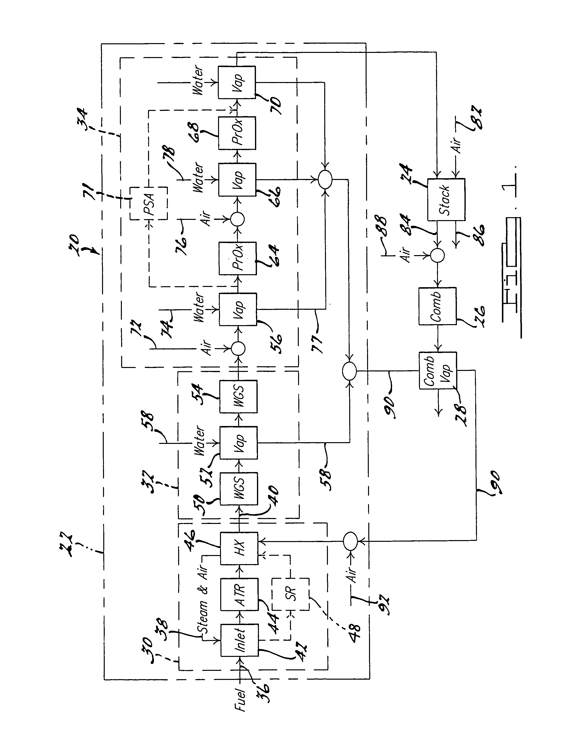
[0023]The present invention is directed to a compact cylindrical vaporizer (heat exchanger) for simultaneous reduction of reformate temperature and process steam generation in a fuel processing system. A fuel cell system 20 utilizing a vaporizer according to the principles of the present invention is shown in FIG. 1. Fuel cell system 20 includes a fuel processing system 22, a fuel cell stack 24, a combustor 26 and a combustor vaporizer 28.

[0024]Fuel processing system 22, according to the principles of the present invention includes a first stage primary reactor 30 operable to produce a reformate stream, a second stage reactor 32 operable to reduce a CO content of the reformate stream, and a third stage or CO-polishing stage reactor 34 operable to further reduce the CO content of the reformate stream.

[0025]Primary reactor...


PUM

PropertyMeasurementUnit
temperatureaaaaaaaaaa

Abstract

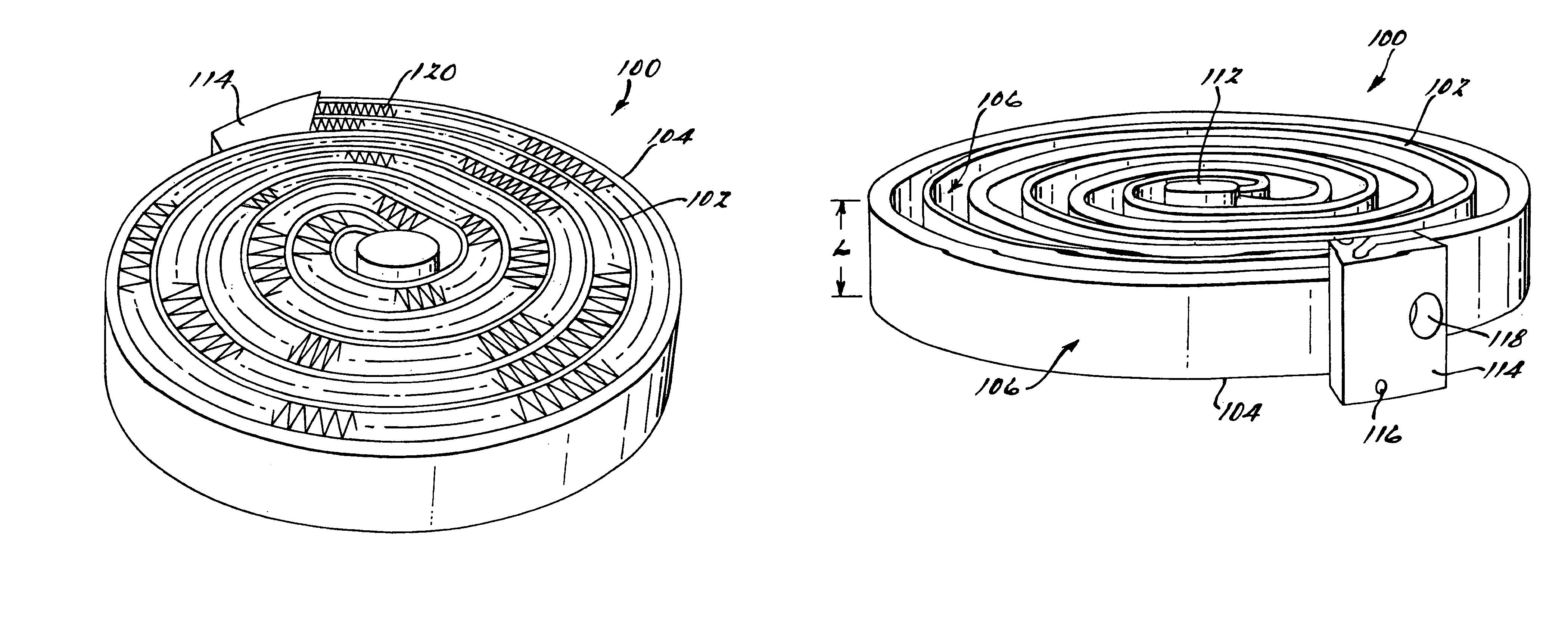
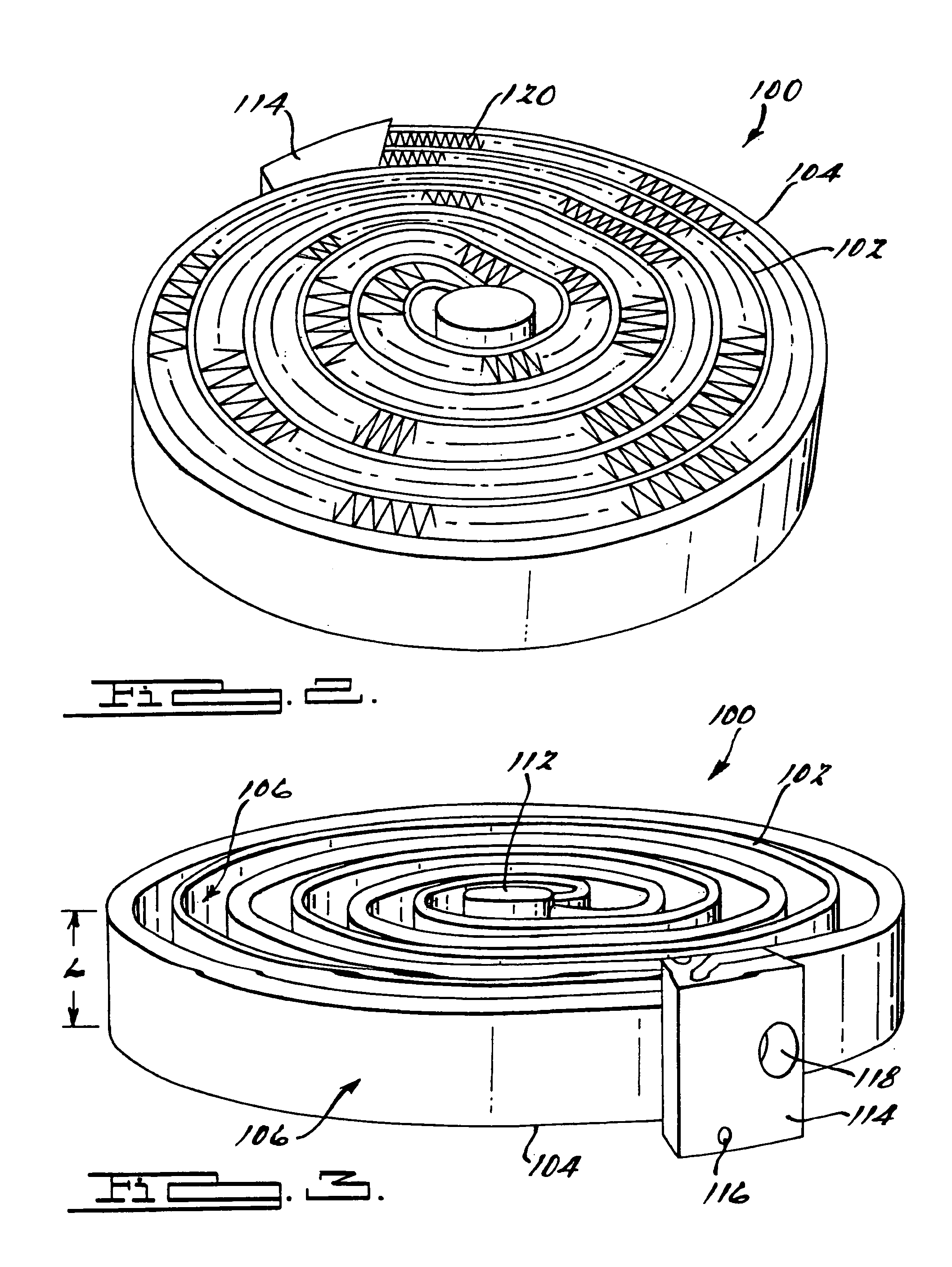
A compact cylindrical vaporizer for simultaneous reduction of a reformate stream temperature and generation of a process stream is disclosed. The vaporizer utilizes counter flowing nested tubular portions that spiral between an outer section of the vaporizer and a central section of the vaporizer. The return spiral has a larger cross-sectional area than the inward spiral to accommodate a higher volumetric flow rate of the water flowing there through as it vaporizes while keeping the fluid velocity below erosion design constraints. The counter spiraling flow provides a substantially uniform spatial temperature profile of a reformate stream flowing on the exterior of the tubular portions. The vaporizer can be sized to be substantially the same as that of an upstream reactor to minimize velocity losses and pressure drops in the reformate stream flowing there through. A plurality of fins are positioned between the opposing tubular portion to enhance the heat transfer.

Description

FIELD OF THE INVENTION[0001]The present invention relates to water vaporizers and, more particularly, to water vaporizers in a fuel reforming process that produces a hydrogen fuel for fuel cells.BACKGROUND OF THE INVENTION[0002]Fuel cells are a leading alternate fuel power plant candidates for both portable and stationary electrical power generation. A fuel cell is an electrical chemical energy converter consisting of two electrodes which sandwich an electrolyte. In one form, an ion-conducting polymer electrolyte membrane (PEM) is disposed between two electrode layers to form a membrane electrode assembly (MEA). The MEA is typically porous and electrically conductive to promote the desired electrochemical reaction from two reactants. One reactant, oxygen or air, passes over one electrode and hydrogen, the other reactant, passes over the other electrode to produce electricity, water and heat. Typical PEM fuel cells with membrane electrode assembly (MEA) are described in U.S. Pat. Nos...

Claims


Application Information

Patent Timeline
Patent Type & Authority Patents(United States)
IPC IPC(8): F22B1/02B01B1/00C01B3/38C01B3/48C01B3/56F28D1/047F28F1/02F28F1/12
CPCB01B1/005C01B3/38C01B3/382C01B3/48C01B3/56F28D1/0473F28F1/022F28F1/128C01B2203/0233C01B2203/0244C01B2203/0288C01B2203/043C01B2203/044C01B2203/047C01B2203/066C01B2203/0833C01B2203/0844C01B2203/0894C01B2203/1241C01B2203/1247C01B2203/141C01B2203/142C01B2203/145C01B2203/146C01B2203/1614C01B2203/1638C01B2203/82F28D2021/0043
Inventor BURCH, STEVEN DMIGLIORE, THOMAS PODDI, FREDERICK V
Owner GM GLOBAL TECH OPERATIONS LLC
Learn More