Over power compensation in switched mode power supplies

a power supply and switching mode technology, applied in the field of switching mode power supplies, can solve problems such as propagation delay inside the current sense circui

Active Publication Date: 2010-05-20
SEMICON COMPONENTS IND LLC
View PDF4 Cites 106 Cited by
  • Summary
  • Abstract
  • Description
  • Claims
  • Application Information

AI Technical Summary

Problems solved by technology

However, there are inherent propagation delays inside the ...

Method used


Image

  • Over power compensation in switched mode power supplies
  • Over power compensation in switched mode power supplies
  • Over power compensation in switched mode power supplies

Examples


Embodiment Construction

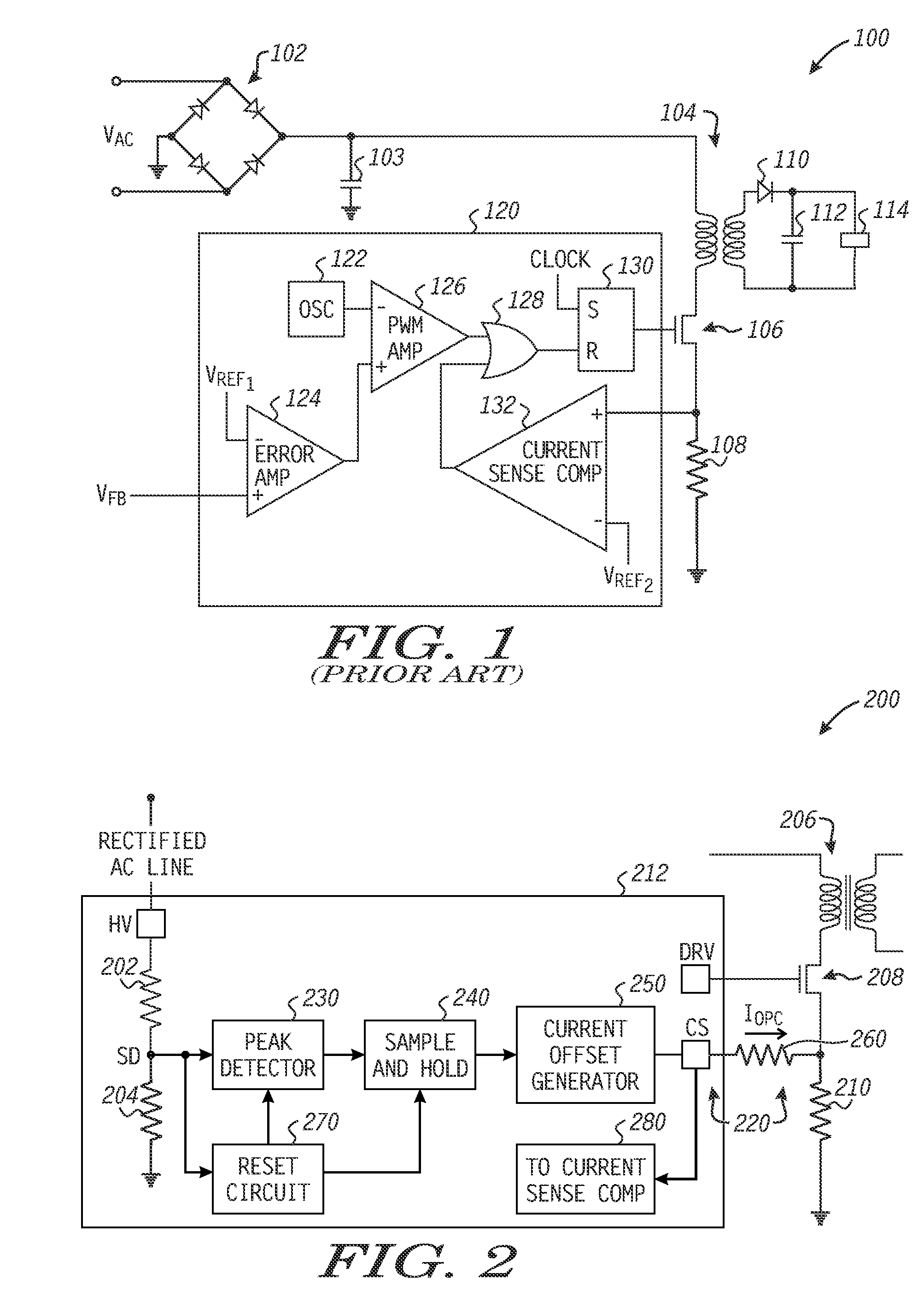
[0012]FIG. 1 illustrates in partial block diagram, partial logic diagram, and partial schematic form a switched mode power supply 100 known in the prior art. Switched mode power supply 100 includes generally a bridge rectifier 102, a capacitor 103, a transformer 104, a power metal oxide semiconductor (MOS) transistor 106, a sense resistor 108, a diode 110, a capacitor 112, a load 114, and an integrated circuit switched mode power supply controller 120. Bridge rectifier 102 has input terminals for receiving a line voltage labeled “VAC”, a first output terminal for providing a rectified voltage, and a second output terminal connected to a ground power supply voltage terminal. Capacitor 103 has a first terminal connected to the first output terminal of rectifier 102, and a second terminal connected to ground. Transformer 104 has a primary winding and secondary winding. The primary winding has a first terminal connected to the first output terminal of rectifier 102, and a second termina...


PUM


Abstract

An over-power compensation circuit for use in a switched mode power supply having a current sense circuit for sensing a current flowing through a power transistor of the switched mode power supply. The over-power compensation circuit includes a peak detector, a sample-and-hold circuit, a current offset generator, and an offset resistor. The peak detector has an input for receiving an input voltage derived from the input line, and an output. The sample-and-hold circuit has an input connected to the output of the peak detector, and an output. The current offset generator has an input connected to the output of the sample-and-hold circuit, and an output for providing an offset current. The offset resistor has a first terminal connected to the output of the current offset generator, and a second terminal adapted to be connected to a current conducting electrode of the power transistor.

Description

FIELD OF THE DISCLOSURE[0001]The present disclosure relates generally to switched mode power supplies, and more particularly relates to over power compensation in switched mode power supplies.BACKGROUND[0002]Power supplies typically include rectifier circuits and transformers for generating a direct current (DC) output voltage from an alternating current (AC) input voltage. Typically, a first rectifier circuit is connected across a primary winding of the transformer, and a power metal oxide semiconductor (MOS) transistor is connected in series with the primary winding of the transformer for driving a current through the primary winding. The first rectifier circuit receives the AC input voltage and provides a rectified voltage to the primary winding of the transformer. A second rectifier circuit is preferably connected across a secondary winding of the transformer and provides the DC output voltage. The DC output voltage can be used to supply operating power to electronic devices suc...

Claims


Application Information

Patent Timeline
IPC IPC(8): G05F1/00
CPCH02M1/32H02M2001/0009H02M3/33507H02M1/0009
Inventor VECERA, IVOKADANKA, PETRCYR, NICOLAS
Owner SEMICON COMPONENTS IND LLC
Why Eureka
Try Eureka