
Network transformer to reduce electromagnetic interference

a technology of electromagnetic interference and network transformer, applied in the direction of waveguide type devices, power distribution line transmission, line-transmission details, etc., to achieve the effect of reducing electromagnetic interferen

Inactive Publication Date: 2010-05-20
RDM TECH
View PDF6 Cites 4 Cited by
  • Summary
  • Abstract
  • Description
  • Claims
  • Application Information

AI Technical Summary

Benefits of technology

[0005]Therefore, the primary object of the present invention is to solve the aforesaid disadvantage by eliminating the high frequency signals to reduce EMI.
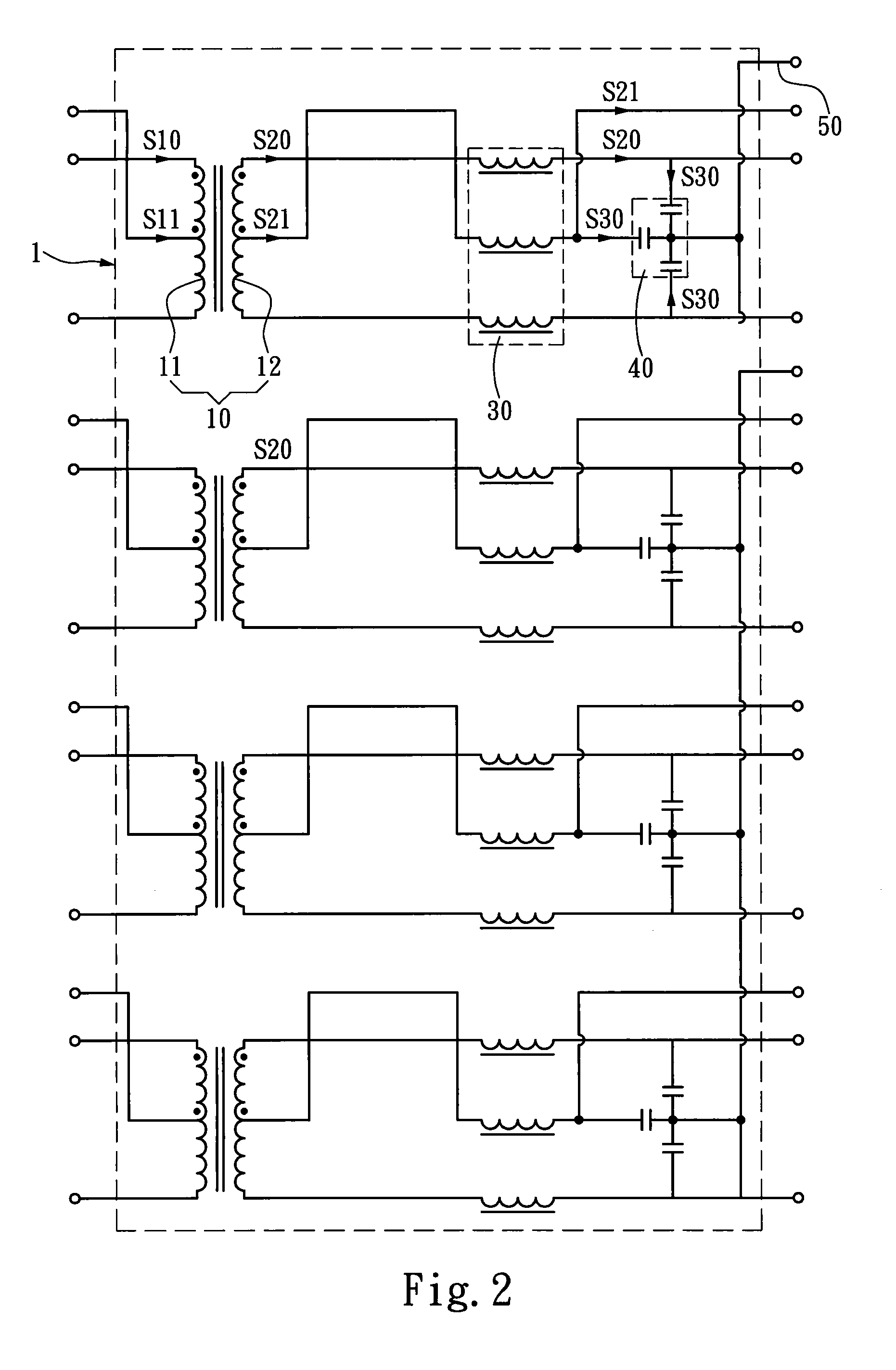
[0006]The present invention provides a network transformer to reduce EMI. It is connected to two network equipment to transmit data. It has a transformation unit, a plurality of high frequency signal attenuation elements electrically connected to the transformation unit and a plurality of high frequency signal channel elements connecting to the high frequency signal attenuation elements. The transformation unit transforms input power and input information of one network equipment to output power and output information, and sends the output power and output information to the high frequency signal attenuation elements to reduce high frequency noises of the output information and output power. Then the attenuated output information and output power are transmitted to the load of the other network equipment. By bridging the high frequency signal channel elements between the high frequency signal attenuation elements and the load, high frequency signals of the output information and output power can be integrated and grounded through the high frequency signal channel elements. Thus the high frequency signals can be eliminated, and EMI can be reduced.

Problems solved by technology

The high frequency signals generate electromagnetic radiation and results in EMI.

Method used


Image

  • Network transformer to reduce electromagnetic interference
  • Network transformer to reduce electromagnetic interference
  • Network transformer to reduce electromagnetic interference

Examples


Embodiment Construction

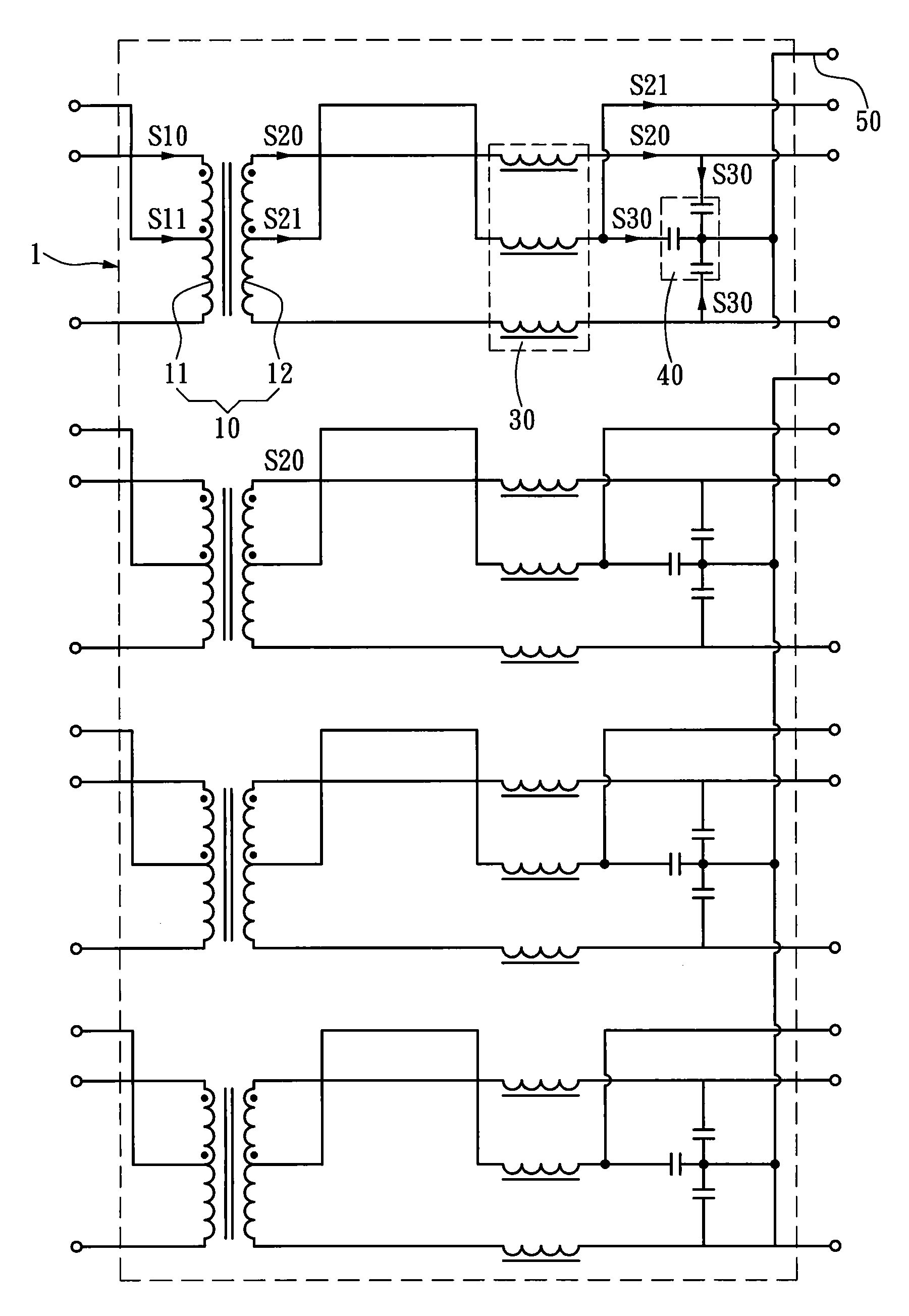
[0012]Please refer to FIG. 2, the network transformer 1 to reduce EMI according to the invention has a plurality of pins at two sides connecting to two network equipment (not shown in the drawing) to transmit data. It includes a transformation unit 10, a plurality of high frequency signal attenuation elements 30 and a plurality of high frequency signal channel elements 40. The transformation unit 10 receives input power S10 and input information S11 from one network equipment (not shown in the drawing) and transforms them to output power S20 and output information S21. The high frequency signal attenuation elements 30 are electrically connected to the transformation unit 10, and receive the output power S20 and output information S21, and reduce high frequency noises of the output information S21 and output power S20. Then the attenuated output information S21 and output power S20 are transmitted to the load of the other network equipment (not shown in the drawing). The high frequen...


PUM


Abstract

A network transformer to reduce electromagnetic interference (EMI) is connected to two network equipment to transmit data. It has a transformation unit to transform input power and input information of one network equipment to output power and output information and a plurality of high frequency signal attenuation elements to receive the output power and output information and reduce high frequency noises thereof. The attenuated output information and output power are sent to the load of the other network equipment. The high frequency signal attenuation elements and the load are bridged by high frequency signal channel elements which receive high frequency signals of the output information and output power, and integrate and ground the high frequency signals. Therefore, the high frequency signals are eliminated and EMI is reduced.

Description

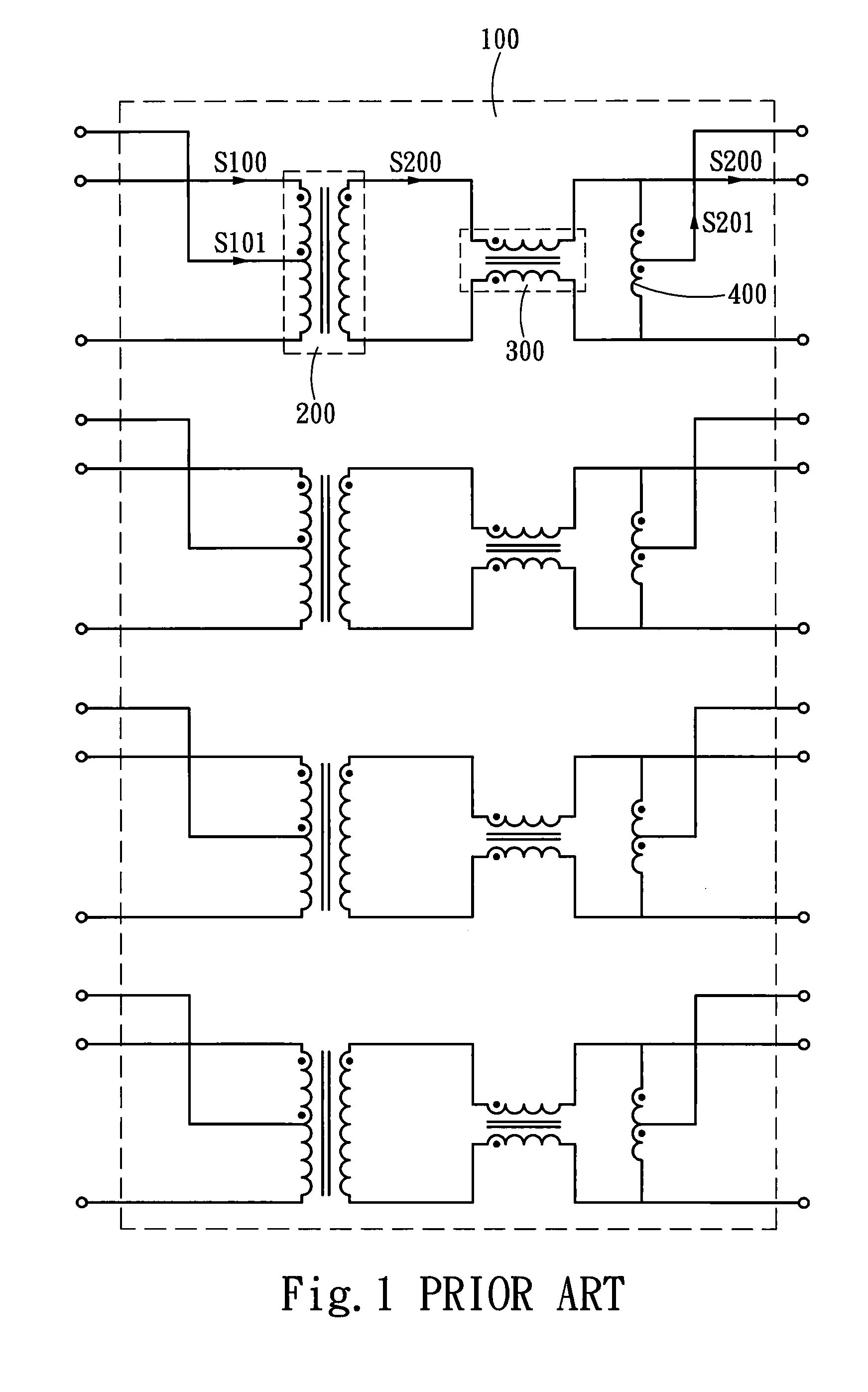
FIELD OF THE INVENTION[0001]The present invention relates to a network transformer and particularly to a network transformer to reduce electromagnetic interference (EMI).BACKGROUND OF THE INVENTION[0002]A conventional network transformer usually is installed between a client interface and a network transceiver chip to transmit data to other ends connected to a network through coupling of internal electromagnetic field. It also has internal coils coupled to do filtering to boost signal intensity to prevent different voltages or currents to pass through different network equipment to cause damages of the equipment resulting from network connection.[0003]Refer to FIG. 1 for a conventional network transformer and its circuit structure. The network transformer 100 has a transformation unit 200, a choke coil 300 connecting to the transformation unit 200 and an induction coil 400 connecting to the choke coil 300. The transformation unit 200 receives input power S100 and input information S...

Claims


Application Information

Patent Timeline
IPC IPC(8): H04B3/28H03H7/09
CPCH01F27/42H03H1/0007H04B2203/5491H04B3/54H03H7/09
Inventor YU, HSIAO-CHI
Owner RDM TECH
Learn More