Multi-Band Antenna

a multi-band antenna and antenna technology, applied in the field of antennas, can solve the problems of reducing the size of the antenna, exposing disadvantages, and all the antennas cannot meet the demand of operating at multiple frequencies, and achieve the effect of reducing the size of the multi-band antenna and occupying a smaller spa

Inactive Publication Date: 2010-05-20
CHENG UEI PRECISION IND CO LTD
View PDF1 Cites 20 Cited by
  • Summary
  • Abstract
  • Description
  • Claims
  • Application Information

AI Technical Summary

Benefits of technology

[0008]As described above, the arrangement of the first radiating portion and the second radiating portion makes the multi-band antenna transmit and receive multiple bands. The feeding portion and the grounding portion are separated by the slot, the radiating part of the second radiating portion is designed as a substantial stair-shape structure, which reduces the size of the multi-band antenna and makes the multi-band antenna take up smaller space when assembled in a portable wireless communication device.

Problems solved by technology

However, all of these antennas could not meet the demand of operating at multiple frequencies while the sizes thereof are reduced.
Therefore, a disadvantage is exposed that covering multiple frequencies and occupying smaller space could not concurrent.

Method used


Image

  • Multi-Band Antenna
  • Multi-Band Antenna

Examples


Embodiment Construction

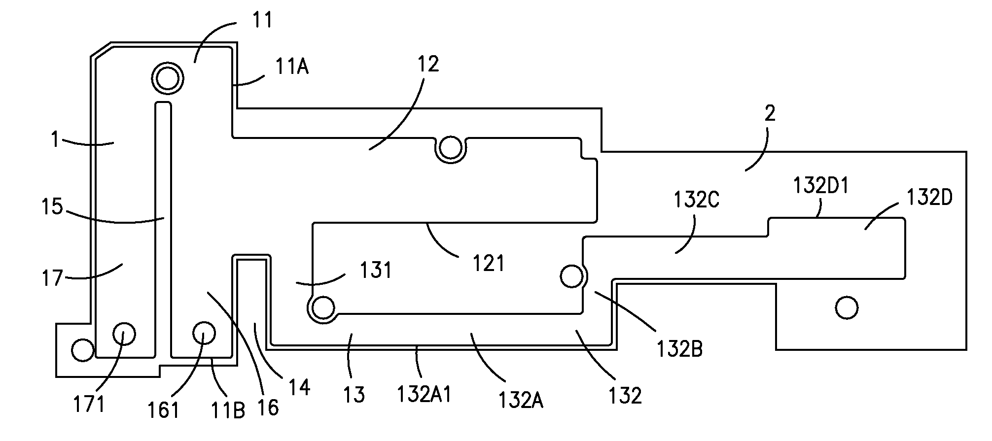
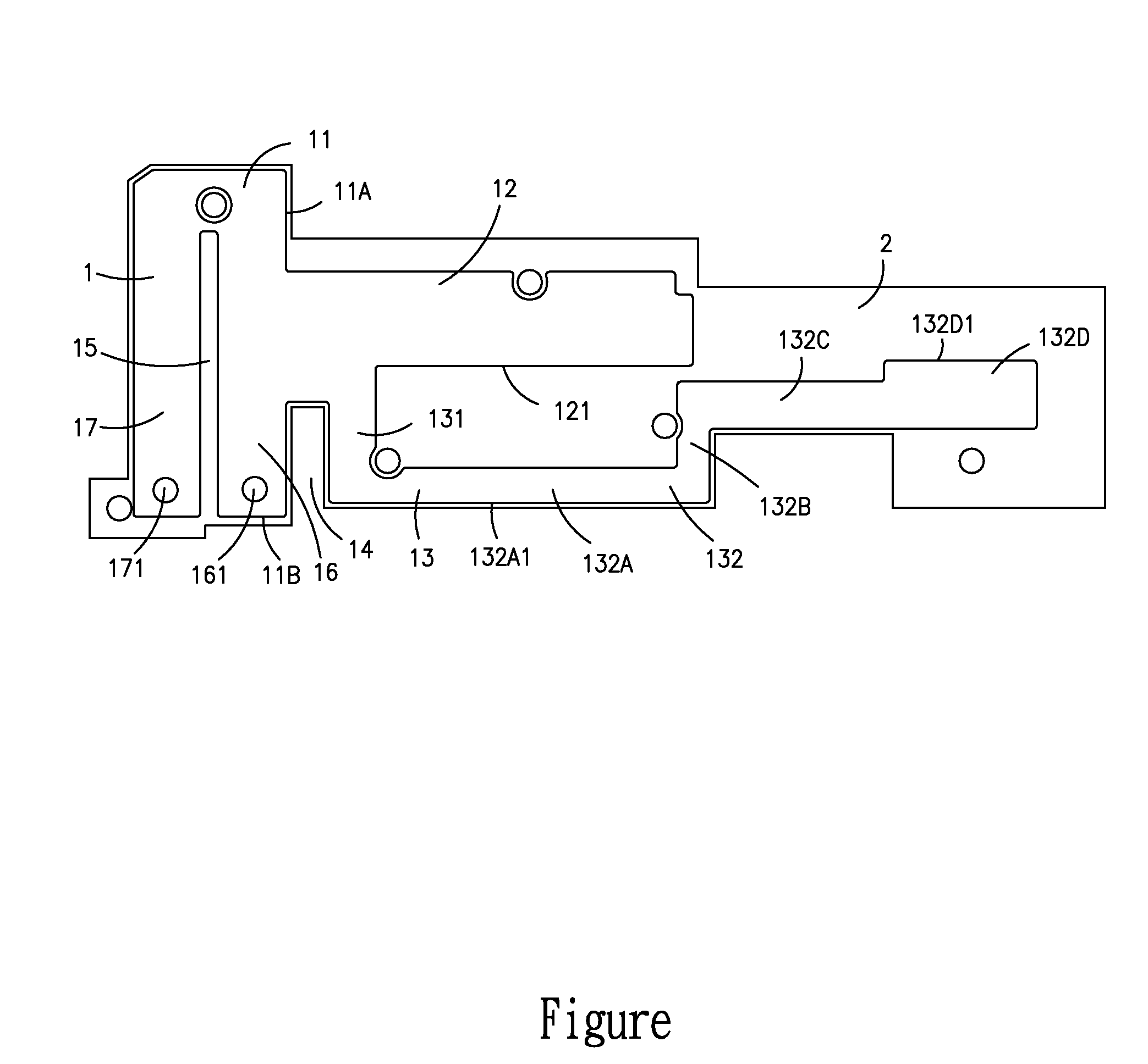
[0011]With reference to FIGURE, a multi-band antenna 1 according to the invention is etched by a flexible printed circuit board 2. The multi-band antenna 1 includes a substantially rectangular base plate 11 which defines a first edge 11A and a second edge 11B perpendicularly connected with the first edge 11A.

[0012]The base plate 11 has an elongated slot 15 longitudinally extending at a middle portion thereof and substantially parallel to the first edge 11A. The slot 15 penetrates through the second edge 11B to divide the base plate 11 into a grounding portion 17 and a feeding portion 16 which defines the first edge 11A as a long edge thereof. The feeding portion 16 defines a feeding point 161 adjacent to the second edge 11B, the grounding portion 17 defines a grounding point 171 adjacent to the second edge 11B too. The feeding portion 16 and the grounding portion 17 form a simulation inductance therebetween for tuning bandwidth and input impedance of the multi-band antenna 1 to real...


PUM


Abstract

A multi-band antenna has a base plate which defines a slot longitudinally extending and penetrating through one edge of the base plate to divide the base plate into a feeding portion and a grounding portion. A first radiating portion extends substantially perpendicularly from the feeding portion. A second radiating portion includes a connecting section substantially perpendicularly extending from the first radiating portion and substantially parallel and adjacent to the base plate and a radiating part connected with the connecting section and opposite to the base plate. The radiating part has a first radiating strip, a second radiating strip, a third radiating strip and an extended radiating strip, all of which shows a substantial stair-shape in combination.

Description

BACKGROUND OF THE INVENTION[0001]1. Field of the Invention[0002]The present invention relates to an antenna, and more particularly to a multi-band antenna.[0003]2. The Related Art[0004]In recent years, portable wireless communication devices are becoming progressively popular. In order to communicate with other communication devices, various antennas are assembled in these devices for transmitting and receiving electromagnetic waves. Considering the miniaturization trend of the portable wireless communication device, the size of the antenna should be correspondingly reduced in order to be assembled in the limited space of the portable wireless communication device.[0005]Among present wireless technologies, wireless communication bands include global system for mobile communications (GSM) band about 850 MHz, extended global system for mobile communications (EGSM) band about 900 MHz, digital cellular system (DCS) band about 1800 MHz, personal conferencing specification (PCS) band abou...

Claims


Application Information

Patent Timeline
Patent Type & Authority Applications(United States)
IPC IPC(8): H01Q1/38
CPCH01Q1/38H01Q5/371H01Q9/42
Inventor SU, JIA-HUNGTSAI, YUNG-CHIHSHIH, KAIWU, YU-YUAN
Owner CHENG UEI PRECISION IND CO LTD
Why Eureka
Try Eureka