
Layout method

a technology of layout and construction, applied in the direction of distance measurement, instruments, surveying and navigation, etc., can solve the problems of requiring a significant amount of labor to lay out construction, affecting the quality of construction,

Active Publication Date: 2010-05-20
TRIMBLE NAVIGATION LTD
View PDF10 Cites 63 Cited by
  • Summary
  • Abstract
  • Description
  • Claims
  • Application Information

AI Technical Summary

Benefits of technology

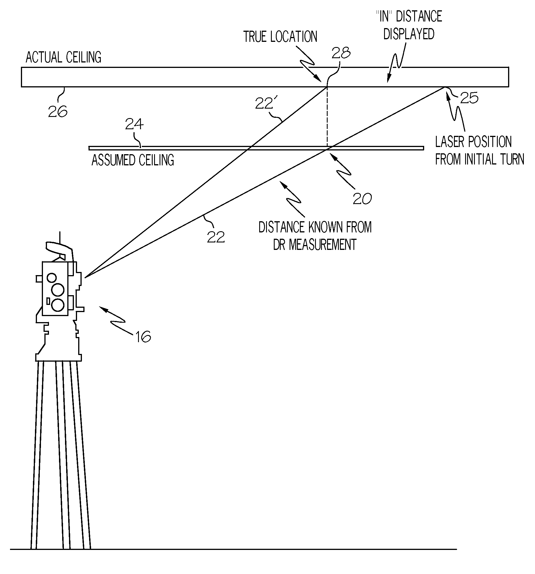
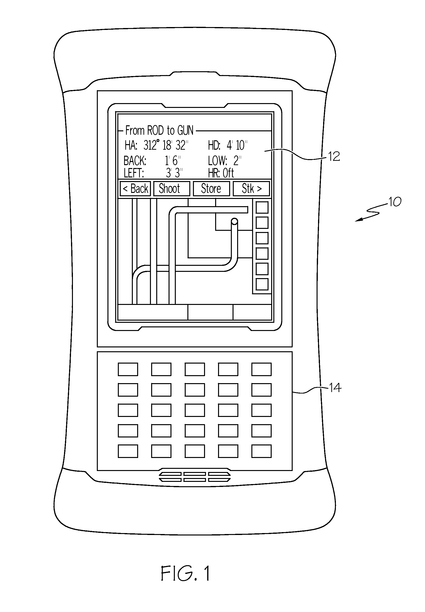
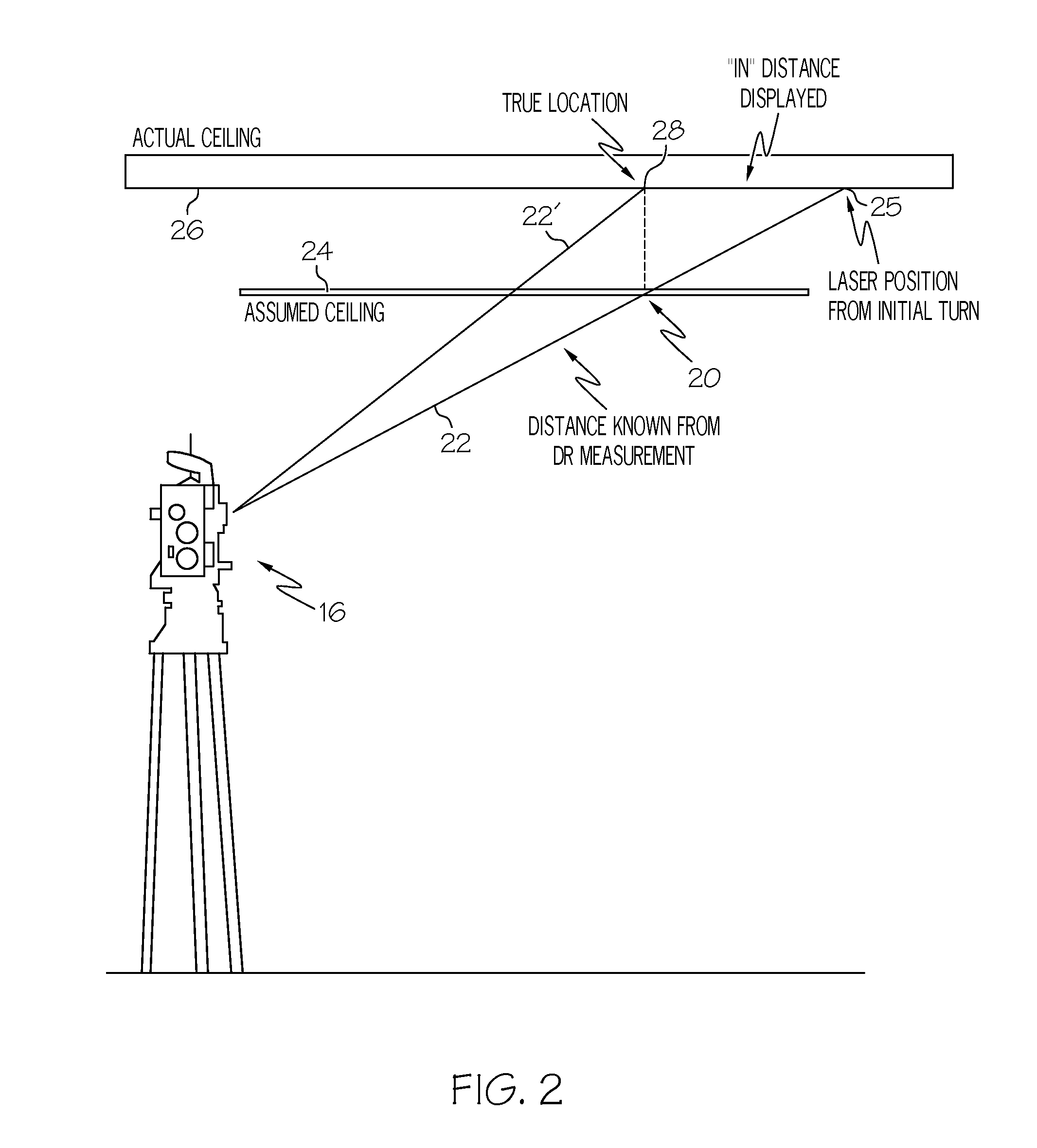
[0009]A method of establishing the location of one of a series of construction points at an indoor construction site, where the point is defined by x and y coordinates and an anticipated z coordinate on a generally horizontal building surface, with the construction point being established on an actual building surface by illumination of a point on the actual building surface that has the x and y coordinates, includes the steps of inputting construction data into a handheld device, the construction data defining a plurality of construction points at the construction site, and selecting one of the plurality of construction points with the handheld device. A beam of light is generated with a robotic total station, and the beam is directed from the robotic total station toward the selected construction point, defined by the x and y coordinates and the anticipated z coordinate on a generally horizontal building surface. ...

Problems solved by technology

Laying out mechanical, electrical and plumbing systems in new buildings under construction, or in existing buildings undergoing renovations or additions, is tedious, time consuming, and expensive.
Typically, it has required a significant amount of labor to lay out construction points at a construction site for sleeves and hangers on floors and ceilings.
It will be appreciated that such a process is subject to errors, both from measurement mistakes and from accumulated errors which compound as measurements are made from one intermediate point to the next.
Further, building designs and requirements have become more complex, and construction schedules have become tighter, adding to the need to facilitate and simplify the layout process.

Method used


Image

  • Layout method
  • Layout method
  • Layout method

Examples


Embodiment Construction

[0018]The described methods may be advantageously used in establishing the locations of construction points at an indoor construction site. As an example, during the construction of a building, HVAC contractors must locate and install pipes and ducts above, below, and through ceilings and floors. For such building components, the contractor is typically given a blueprint of the ducts, pipes, and points to affix hangers on the ceilings and floors for securing pipes and ducts, with the x and y positions of the various points. Typically, the contractor must project the blueprint design taken from the paper document, onto the floor or ceiling. Workers typically use power lift equipment, such as a cherry picker, to measure these points on a ceiling for attaching hangers, for example. This is a very time consuming task, especially when a large building or building complex, such as a shopping mall, is being constructed, and many construction points must be measured and marked.

[0019]The pre...


PUM


Abstract

The location of one of a series of construction points at an indoor construction site is established using a robotic total station and a handheld device. Construction data is inputted into the handheld device with the construction data defining a plurality of construction points at the construction site. One of the plurality of construction points is selected with the handheld device. Data regarding the selected construction point is then transmitted wirelessly from the handheld device to a robotic total station. The robotic total station generates a beam of laser light, and directs the beam of laser light from the robotic total station to the construction point. The construction point is defined by x and y coordinates, and by an assumed z coordinate. The actual z coordinate is that of a point on a horizontal surface, such as a ceiling or floor, having the same x and y coordinates. Through an iterative process, the location of the construction point is established.

Description

CROSS-REFERENCE TO RELATED APPLICATION[0001]Not applicable.STATEMENT REGARDING FEDERALLY SPONSORED RESEARCH OR DEVELOPMENT[0002]Not applicable.BACKGROUND OF THE INVENTION[0003]Laying out mechanical, electrical and plumbing systems in new buildings under construction, or in existing buildings undergoing renovations or additions, is tedious, time consuming, and expensive. Typically, it has required a significant amount of labor to lay out construction points at a construction site for sleeves and hangers on floors and ceilings. This process has required teams of workers that measure and mark the locations of these points, with much of the work being accomplished manually. It will be appreciated that such a process is subject to errors, both from measurement mistakes and from accumulated errors which compound as measurements are made from one intermediate point to the next. Further, building designs and requirements have become more complex, and construction schedules have become tight...

Claims


Application Information

Patent Timeline
IPC IPC(8): G01C3/08
CPCG01C15/002
Inventor MILLER, ROBERTSMITH, LAWRENCE
Owner TRIMBLE NAVIGATION LTD
Learn More