

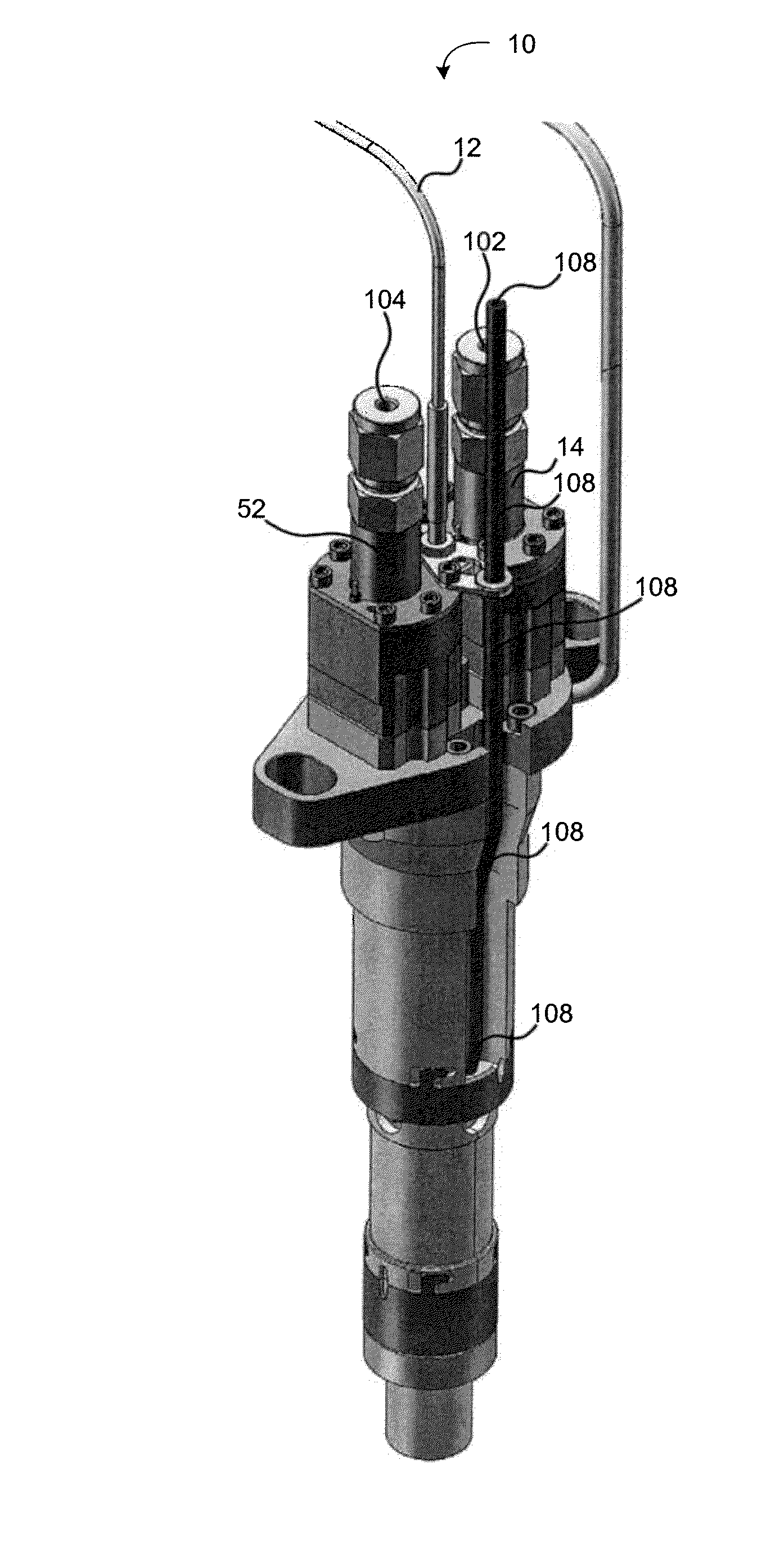
Dual solenoid fuel injector with catalytic activator section
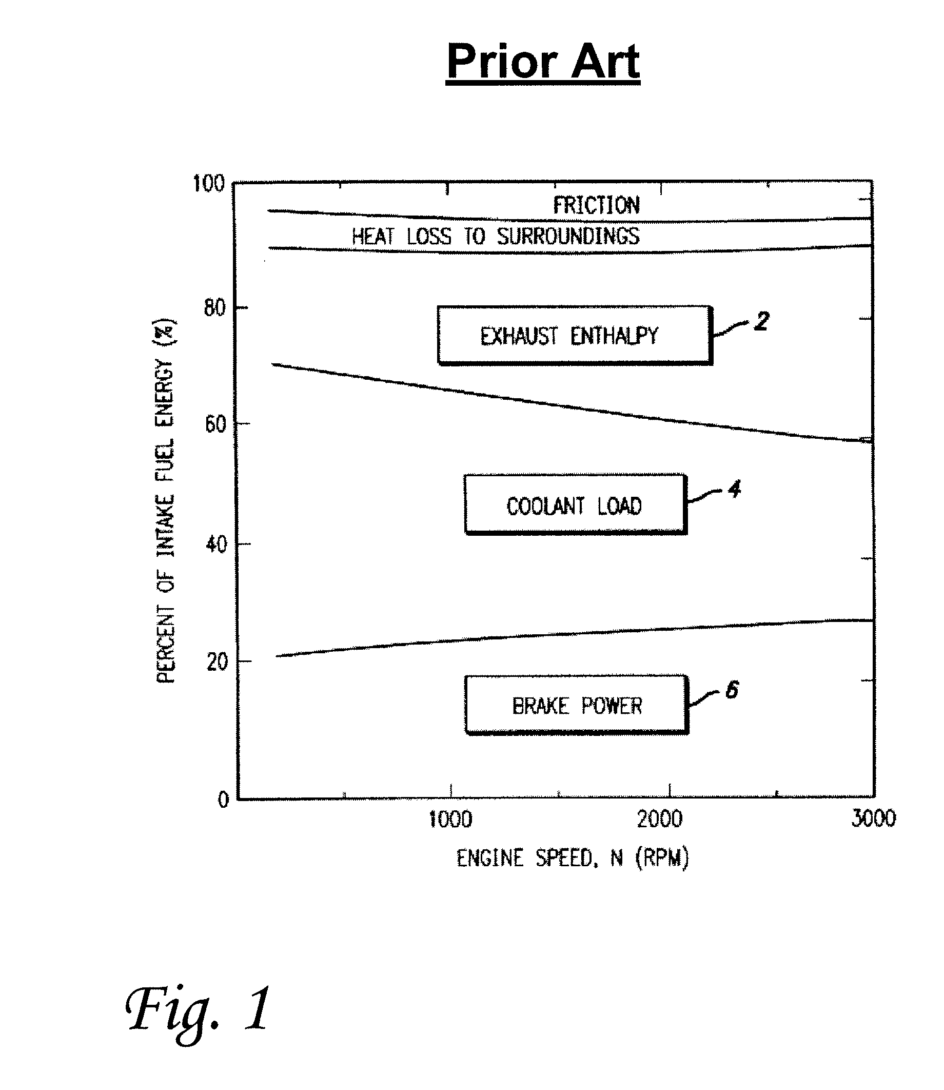
a fuel injector and solenoid technology, applied in the direction of fuel injection apparatus, charge feed system, coating, etc., can solve the problems of consuming global resources, consuming a lot of pollutants and greenhouse gases, and the conventional combustion process inside a spark ignition gasoline engine or compression ignition diesel engine takes a long time, so as to achieve more efficient combustion of fuel
- Summary
- Abstract
- Description
- Claims
- Application Information
AI Technical Summary
Benefits of technology
Problems solved by technology
Method used
Image

Examples
Embodiment Construction
[0024]In the following paragraphs, the present invention will be described in detail by way of example with reference to the attached drawings. Throughout this description, the preferred embodiment and examples shown should be considered as exemplars, rather than as limitations on the present invention. As used herein, the “present invention” refers to any one of the embodiments of the invention described herein, and any equivalents. Furthermore, reference to various feature(s) of the “present invention” throughout this document does not mean that all claimed embodiments or methods must include the referenced feature(s).
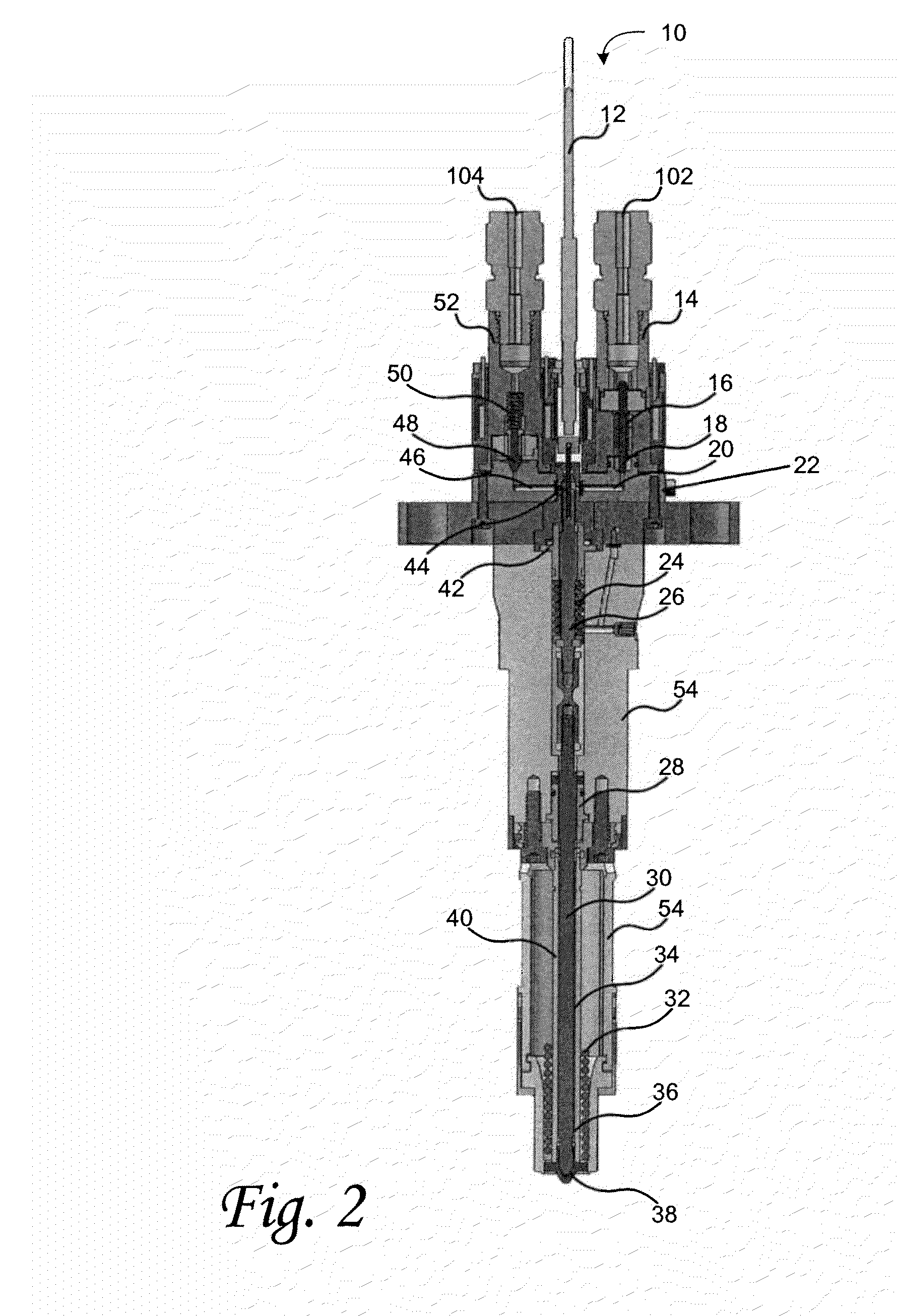
[0025]In accordance with the principles of the present invention, an internal combustion engine fuel injector having a hydraulically actuated injection pin, also referred to herein as an injector stem, is provided. According to various embodiments of the invention, the fuel injector achieves efficient fuel combustion by (i) fast and responsive actuation, (ii) heating...
PUM
 Abstract
Description
Claims
Application Information