Airway device

a technology of airway and spleen, which is applied in the field of spleen airway devices, can solve the problems of inability to effectively cough, direct or indirect mortality, significant and varying degrees of co-morbidity, etc., and achieve the effect of appealing and practical design

Active Publication Date: 2010-05-27
NASIR MUHAMMED ASLAM
View PDF103 Cites 36 Cited by
  • Summary
  • Abstract
  • Description
  • Claims
  • Application Information

AI Technical Summary

Benefits of technology

[0029]Accordingly, according to a first embodiment, there is provided an airway device for human or animal use comprising an airway tube having a distal end and a proximal end, the distal end of which is surrounded by a laryngeal cuff, characterised in that the laryngeal cuff is adapted to form an anatomical fit over the laryngeal inlet of a patient, and to cover and form a substantially gas-tight seal with the laryngeal inlet of the patient, the device further comprising a buccal cavity stabiliser located on or around the airway tube between the laryngeal cuff and the proximal end of the tube, said buccal cavity stabiliser being adapted to nest with the anterior aspect of the patient's tongue, the size, shape, softness and configuration of the buccal stabiliser being adapted to provide stability and to prevent rotational or side-to-side movement of the airway tube in use. This buccal cavity stabiliser may be formed from the same material as the cuff or from a different material and assists in locating and maintaining the position of the device in use.
[0073]Preferably the face of the laryngeal cuff adapted to form an anatomical fit over the laryngeal inlet of a patient incorporates protuberances designed to form a good seal with the valleculae, epiglottis, aryepiglottic folds, pyriform fossae and around the anterior aspect of thyroid & cricoid cartilages. The distal tip of the device positions itself into the recess created by the posterior aspect of the lower larynx below the posterior cartilages, above the opening of the oesophagus, not only to help create an airway seal but also to act as a physical wedge to prevent the possibility of regurgitation.

Problems solved by technology

All of the above mentioned devices carry significant and varying degrees of co-morbidity involving not only unacceptable concurrent physiological changes but also temporary and / or permanent anatomical / structural damage.
Many cases of mortality caused directly or indirectly as a result of the use of such devices have also been reported.
The undesirable aspects of intubation of the trachea result from the fact that, to effect a seal, pressure is applied to an epithelial surface whose important and highly specialized functions are thus compromised and that by penetration of the vocal cords, effective coughing is rendered impossible, upper-airway architecture is distorted and unwanted reflex response are not only provoked by laryngoscopy needed prior to intubation but also by presence of endotracheal tube in the trachea.
Several attempts have been made to improve this type of airway device but they still suffer from a number of serious inherent drawbacks.
Firstly, they require inflation of the cuff to be effective and furthermore anaesthetic gas (nitrous oxide) can diffuse into the cuff, expanding the air in the cuff, thus increasing the cuffs extraluminal pressure significantly, and as a result, put considerable pressure on the sensitive tissues of Laryngopharynx.
Secondly, these masks have a tendency to move from side to side or rotate about their longitudinal axis as a force is applied to the proximinal end of the tube, attached to the anaesthetic equipment.
However, any rotational or sideways movement of the airway tube will have the potential to affect the seal that the airway device makes around the laryngeal inlet.
However, this relies on an inflatable oro-pharyngeal cuff that suffers from the disadvantages referred to above.
However, not only does this suffer from all the disadvantages of an inflatable cuff device, but it is formed from multiple components, adding to the cost and complexity of manufacture.
In fact there are several applications where it is just not practical to have a buccal cavity stabiliser.

Method used


Image

  • Airway device
  • Airway device
  • Airway device

Examples


Embodiment Construction

[0139]Embodiments of the present invention are described below by way of example only. These examples represent the best ways of putting the invention into practice that are currently known to the applicant although they are not the only ways in which this could be achieved.

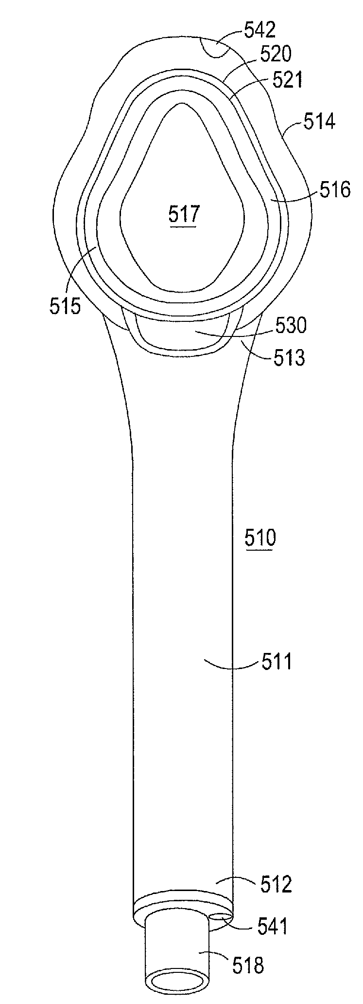
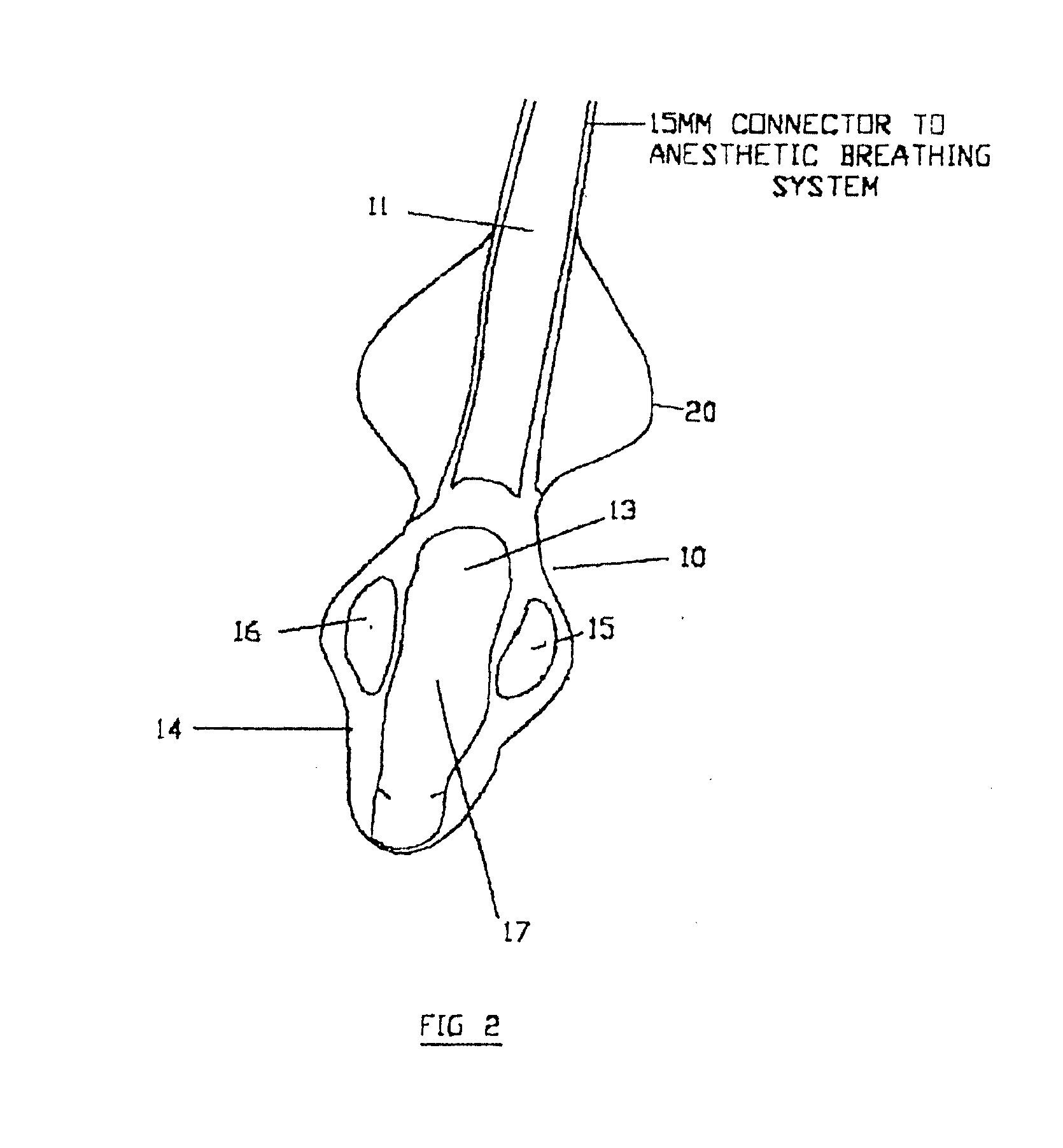
[0140]Referring to FIG. 2, this illustrates the distal end of a mask device according to a first embodiment of the present invention, generally shown as 10. This comprises an airway tube 11, which at its proximal end 12 (not shown) terminates in a 15 mm or other connector suitable for connection to an anaesthetic breathing system of conventional type. Formed around the distal end 13 of the airway tube is a laryngeal cuff or cup 14 adapted in its shape and contours to correspond with the larynx inlet region of a patient. In this context the terms cuff and cup have an equivalent meaning. They refer to the element of the device at the distal end of the airway tube that is adapted to cover and form a seal with the la...


PUM

PropertyMeasurementUnit
Shore hardnessaaaaaaaaaa
pressureaaaaaaaaaa
pressureaaaaaaaaaa

Abstract

An airway device for human or animal use comprising an airway tube having a distal end and a proximal end, the distal end of which is surrounded by a laryngeal cuff, adapted to fit anatomically over the laryngeal structure of a patient, wherein the device optionally further comprises a buccal cavity stabiliser located on or around the airway tube between the laryngeal cuff and the proximal end of the tube, said buccal cavity stabiliser being adapted to nest with the anterior aspect of the patient's tongue, the size, shape and configuration of the buccal stabiliser being adapted to prevent rotational or side-to-side movement of the airway device in use.

Description

FIELD OF THE INVENTION[0001]This invention relates to an anatomically oriented, simple but versatile, improved airway device. It is particularly applicable, but in no way limited, to devices used in the administration of anaesthetics to a patient breathing spontaneously during a surgical procedure. The present invention relates in particular to a laryngeal airway device. More specifically, the present invention relates to reduced cost, disposable laryngeal airway device, and to methods of fabricating such airway device.BACKGROUND TO THE INVENTION[0002]Examples of devices currently used in spontaneously breathing anaesthetized patients, during recovering after anaesthetics, weaning of a certain group of patients in intensive care, or during resuscitation to provide a clear and hands-free airway are:[0003]a) Guedel airway with various types of face masks.[0004]b) Cuffed Oro-pharyngeal airway.[0005]c) Laryngeal Mask Airway (LMA), reinforced LMA, intubating LMA and a modified Intavent L...

Claims


Application Information

Patent Timeline
Patent Type & Authority Applications(United States)
IPC IPC(8): A61M16/04
CPCA61M16/04A61M16/0402B29C45/1676B29K2995/007B29L2031/753A61M2207/00A61M16/0415A61M16/0431A61M16/0436A61M16/0486A61M16/0434A61M16/0409A61M16/0445A61M16/0493
Inventor NASIR, MUHAMMED ASLAM
Owner NASIR MUHAMMED ASLAM
Why Eureka
Try Eureka