Connection structure of wave-shaped synthetic resin pipes, wave-shaped synthetic resin pipes used for the connection structure, and manufacturing method thereof

a technology of synthetic resin pipes and connection structures, applied in the direction of pipe connection arrangements, pipe elements, mechanical equipment, etc., can solve the problems of reducing the operating efficiency, affecting the sealing performance of the pipe, so as to improve the sealing performance, prevent displacement, and increase the strength of the socket

Active Publication Date: 2010-05-27
KANA FURETSUKUSU KOOHOREESHON
View PDF13 Cites 23 Cited by
  • Summary
  • Abstract
  • Description
  • Claims
  • Application Information

AI Technical Summary

Benefits of technology

[0031]The pipe material and the end of the second corrugated synthetic resin pipe are integrated together with the synthetic resin layer disposed therebetween. This increases the strength of the socket, and prevents displacement between the pipe material and the pipe end in the axial direction, thereby improving sealing performance.
[0032]The socket includes a pipe material having a large diameter and projecting coaxially with the corrugated synthetic resin pipe, and the synthetic resin material is injected into the gaps between the pipe material and the corrugated synthetic resin pipe. This increases the strength of the socket, thereby providing the connection structure having higher resistance to water and pressure.
[0033]The pipe material has a pipe wall formed in a spirally corrugated shape similar to the pipe wall of the corrugated synthetic resin pipe. This increases the strength of the pipe material. The synthetic resin layer can be adhered to entirely coat the outer surface of the pipe material, but can alternatively be adhered in such a manner that the pipe material is partially exposed. This can reduce the weight and material cost. In addition, the pipe wall of the pipe material has the same appearance as the pipe wall of the corrugated synthetic resin pipe, thereby improving unity between the joint and the entire pipe, and hence, their appearance.
[0034]According to the method for manufacturing the corrugated synthetic resin pipe of the present invention, the pipe material as a component of the socket is formed immediately after the formation of the pipe wall of the corrugated synthetic resin pipe, and the synthetic resin material is injected into the gaps between the pipe material sealed using the sealing chucks and the corrugated synthetic resin pipe. This allows the corrugated synthetic resin pipe and the socket to be formed integrally at the same time, thereby improving production efficiency and decreasing cost.
[0035]At least one of the sealing chucks has an inlet for injecting the synthetic resin material. This facilitates the injecting of the synthetic resin material.
[0036]During formation of the pipe material, continuously fed steel is deformation-processed to have an M-shaped cross section and then spirally discharged, and at the same time, an outer wound tape is continuously spirally discharged so as to be adhered to the outer surface of the steel and integrated in the axial direction, thereby providing the pipe material. This continuous integral molding provides the high-strength pipe material.

Problems solved by technology

This takes a lot of time and effort, thus decreasing the operating efficiency.
It is also troublesome to manage the large number of component parts.
Furthermore, it is a heavy burden for field workers to move two pipes to specific positions of the packing sheets after the packing sheets are laid on the inner surfaces of the half joints.
In addition, the amount of the caulking material to be filled and the degree of stretching the packing sheets in the field vary between individuals, thus causing quality variations.
This connection structure, however, has the following problems.
The connecting flanges, which are required to be connected using bolts and nuts, decrease operating efficiency.
The pipe ends to which the flanges are welded can cause water leakage unless they are made watertight, and deformation of the flange surfaces can also cause water leakage.
Avoiding the water leakage requires high quality in welding, and also in the strength, shape, and size of the flanges, which hinders cost reduction.
Another problem is that the robust flanges, and the bolts and nuts to connect them inevitably increase the weight of the connected areas.
Further another problem is that the connection between the flange surfaces via the packing limits the resistance to water and pressure of the flange surfaces, and requires evenly tightening bolts and nuts, which hinders improving operating efficiency.

Method used


Image

  • Connection structure of wave-shaped synthetic resin pipes, wave-shaped synthetic resin pipes used for the connection structure, and manufacturing method thereof
  • Connection structure of wave-shaped synthetic resin pipes, wave-shaped synthetic resin pipes used for the connection structure, and manufacturing method thereof
  • Connection structure of wave-shaped synthetic resin pipes, wave-shaped synthetic resin pipes used for the connection structure, and manufacturing method thereof

Examples


first embodiment

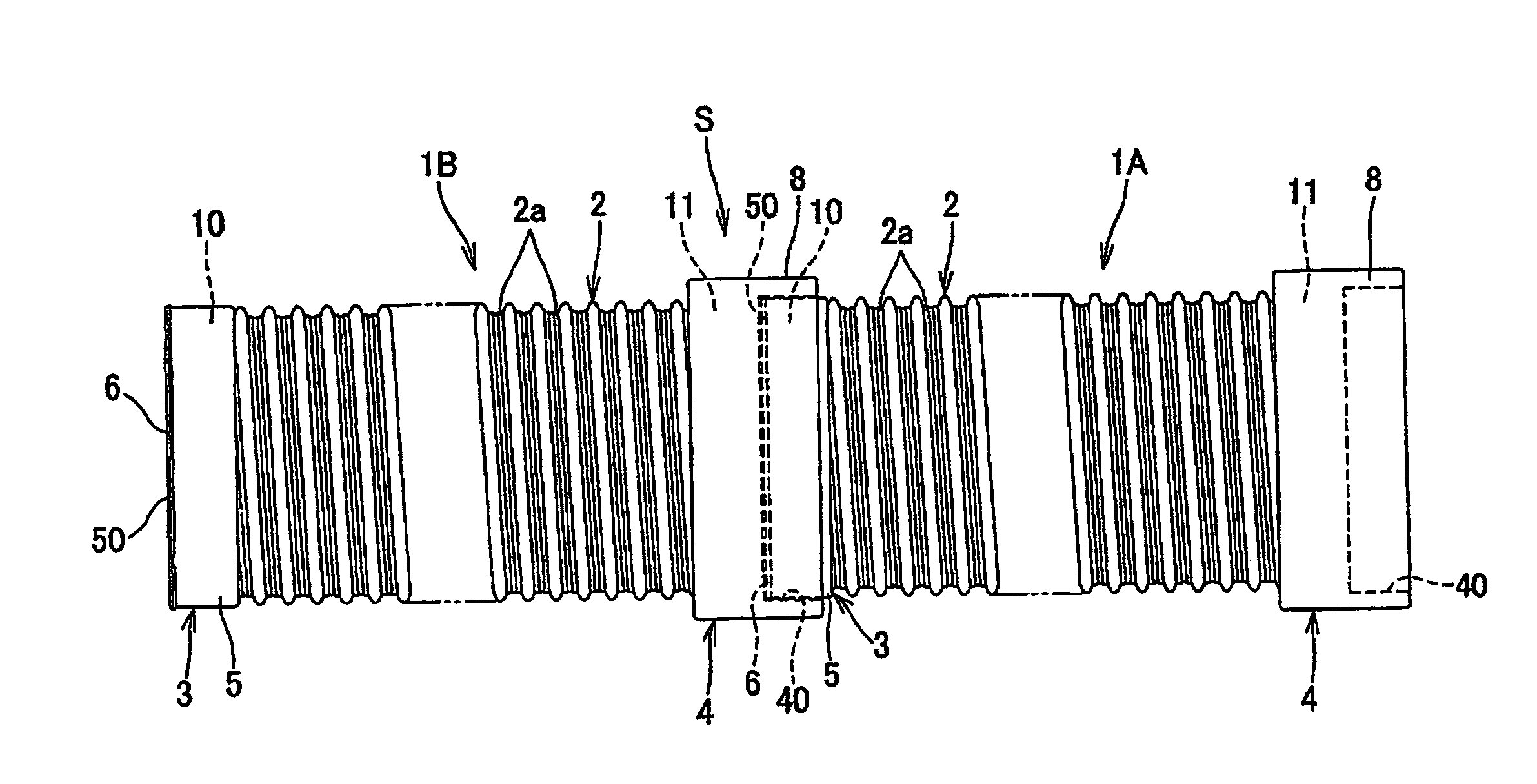
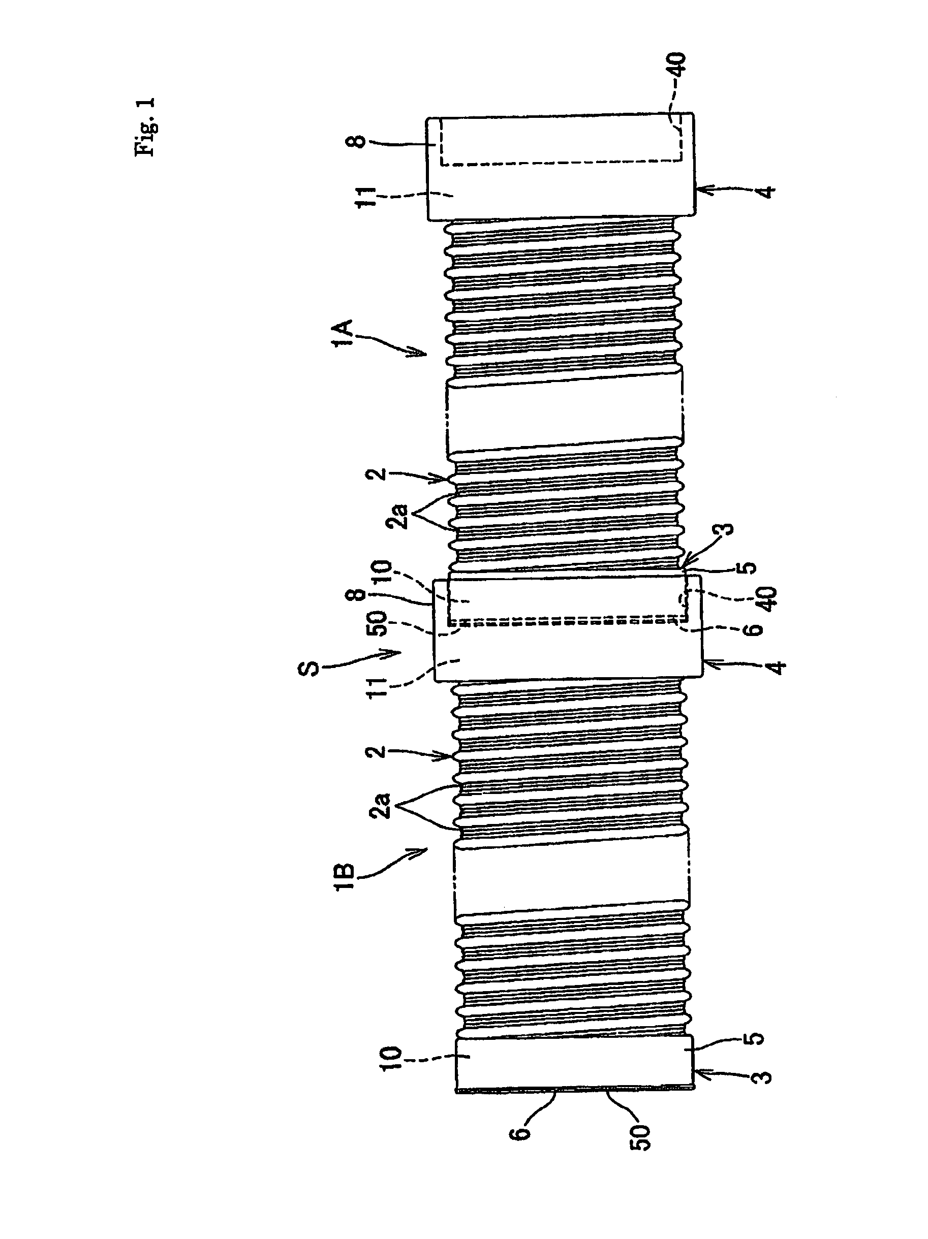
[0056]First, a first embodiment will be described based on FIGS. 1 to 4.

[0057]The corrugated synthetic resin pipes 1A and 1B include the spirally corrugated pipe wall 2, and are provided at the one end 10 (left end in FIG. 1) with the cylindrical insert end 3, and at the other end 11 (right end in FIG. 1) with the socket 4 as shown in FIG. 2. The insert end 3 is formed by adhering a synthetic resin layer to the outer surface of the one end 10 in such a manner as to fill corrugated recesses 2a. The socket 4 is formed by adhering synthetic resin to the outer surface of the other end 11 and cylindrically extending the resin outwardly in the axial direction (rightward in FIGS. 1 and 2).

[0058]As shown in FIG. 3A, the pipe wall 2 of each pipe has a series of waves with peaks and valleys of substantially triangular, substantially arc-shaped, or trapezoidal, and the portions including the valleys between the peaks form recesses 2a. In the present embodiment, the pipe wall 2 includes a body ...

second embodiment

[0071]A second embodiment will be described as follows based on FIGS. 5 and 6.

[0072]In the present embodiment, the synthetic resin layer 8 is adhered in such a manner that the pipe material 7 as a component of the socket 4 is partially exposed. The pipe material 7 is embedded in the synthetic resin layer 8 only on the tip side, which requires strength and on the proximal side, which is important in terms of the integration between the pipe material 7 and the pipe wall 2, and is exposed at the remaining portion. Exposing the pipe material 7 in this manner can reduce the weight and material cost. When the pipe material 7 has the same outer structure as the pipe wall 2 as in the present embodiment, the exposed portion of the socket 4 has the same appearance as the pipe wall 2, thereby improving unity between the joint and the entire pipe, and hence, their appearance. Other configurations and modified examples are the same as those of the first embodiment described above. Therefore the ...

third embodiment

[0073]A third embodiment will be described as follows based on FIGS. 7 and 8.

[0074]In the present embodiment, instead of the pipe material 7, the socket 4 contains reinforcing fiber 7B in its synthetic resin portion (synthetic resin layer 8). The reinforcing fiber 7B is embedded in the form of a woven cloth, a nonwoven cloth, or a resin molding in the present embodiment. This structure significantly reduces the weight and cost, while maintaining the strength, as compared with the example using the pipe material 7. The reinforcing projections 21 of each pipe have the concave depressions 23 at the tops of the peaks as shown in FIG. 3B in the present embodiment. Needless to say, however, the concave depressions 23 can be applied to various corrugated synthetic resin pipes in the same manner as in the first embodiment.

[0075]The reinforcing fiber is preferably glass fiber. When the socket 4 is formed of synthetic resin, the woven cloth, nonwoven cloth or resin molding used as the reinfor...


PUM

PropertyMeasurementUnit
shapeaaaaaaaaaa
connection structureaaaaaaaaaa
diameteraaaaaaaaaa

Abstract

Provided are a connection structure for connecting corrugated synthetic resin pipes and a corrugated synthetic resin pipe used in the connection structure. The pipe is lightweight, low cost, and simply structured with a small number of components, having sufficient resistance to water and pressure, and excellent sealing performance without the use of robust material or requiring high precision, and capable of being easily connected and manufactured. A first corrugated synthetic resin pipe 1A is provided at an end 10 with a cylindrical insert end 3 formed by adhering a synthetic resin layer 5 to the outer surface of the end 10 so as to fill at least corrugated recesses a. A second corrugated synthetic resin pipe 1B is provided at an end 11 with a socket 4 formed by adhering synthetic resin to the outer surface of the end 11 and cylindrically extending the resin outwardly in the axial direction.

Description

BACKGROUND OF THE INVENTION[0001]1. Field of the Invention[0002]The present invention relates to a corrugated synthetic resin pipe including a pipe wall having a spirally corrugated shape, which is used, for example, as an underground drainage pipe or a sewage pipe, and also relates to a method for manufacturing the pipe.[0003]2. Description of the Background Art[0004]Conventionally, Hume concrete pipes have been used as underground drainage pipes and sewage pipes. In recent years, however, it has become popular to use corrugated synthetic resin pipes with a body having a substantially flat inner surface and an outer periphery having reinforcing projections spirally arranged thereon. The corrugated synthetic resin pipes are popular because they are as strong as and more durable, lighter in weight, and simpler in construction than Hume pipes. Two such corrugated synthetic resin pipes are connected to each other as follows. First, half joints each having a connecting flange are attach...

Claims


Application Information

Patent Timeline
Patent Type & Authority Applications(United States)
IPC IPC(8): F16L11/11F16L55/00F16L47/00
CPCF16L11/15F16L25/0036B29C44/1295B29C53/785F16L47/065F16L47/06F16L47/08F16L47/16F16L9/06
Inventor KANAO, SHIGEKI
Owner KANA FURETSUKUSU KOOHOREESHON
Why Eureka
Try Eureka