
Manufacture of top plate for an elastomeric rail fastening assembly

a technology of elastomeric rails and fastening assemblies, which is applied in the direction of railway tracks, ballastways, constructions, etc., can solve the problems of unnecessarily increasing the weight and cost of the top plate, unfavorable flashing and positional variations of the socket, and considerable thickness of the metal backing of the frusto-conical surface of the top pla

Inactive Publication Date: 2010-05-27
DELKOR RAIL
View PDF6 Cites 0 Cited by
  • Summary
  • Abstract
  • Description
  • Claims
  • Application Information

AI Technical Summary

Benefits of technology

[0011]The advantage of the invention is that the use of a single core to define the sockets and the well results in the positioning of the sockets in relation to one another and to the well, being precisely defined. Also flashing on the top face of the plate is avoided so that previous problems with the bonding of the elastomeric layer to the top face of the plate are avoided without the need for subsequent dressing. As a single core is used, it can be attached securely to the interior of the mould cavity prior to moulding, and, as the core material is readily removed after moulding the wall thickness of the casting backing the frusto-conical surface of the top plate can be made much thinner than hitherto. In consequence, a thinner wall thickness can be utilised without a loss in performance and with a consequential saving in the weight of the casting. In practice, the weight of the casting determines its price and the combination of the reduction in the weight of the top plate together with the reduced requirement for dressing to remove flash, results in a superior top plate which can be marketed at a cheaper price than hitherto.

Problems solved by technology

Manufacturing a top plate by the method described above results in undesirable flashing and positional variations of the sockets, and those imperfections have to be removed by dressing the casting.
This results in a considerable thickness of the metal backing of the frusto-conical surface of the top plate.
This substantially increases the weight and cost of the top plate unnecessarily.

Method used


Image

  • Manufacture of top plate for an elastomeric rail fastening assembly
  • Manufacture of top plate for an elastomeric rail fastening assembly
  • Manufacture of top plate for an elastomeric rail fastening assembly

Examples


Embodiment Construction

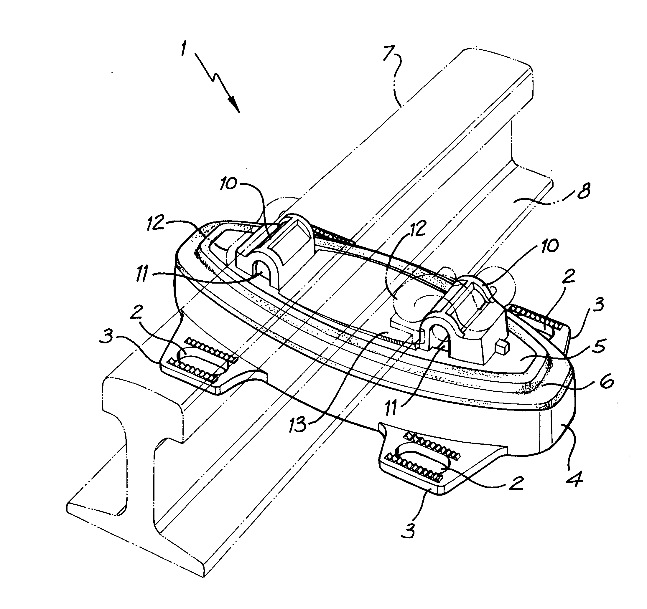
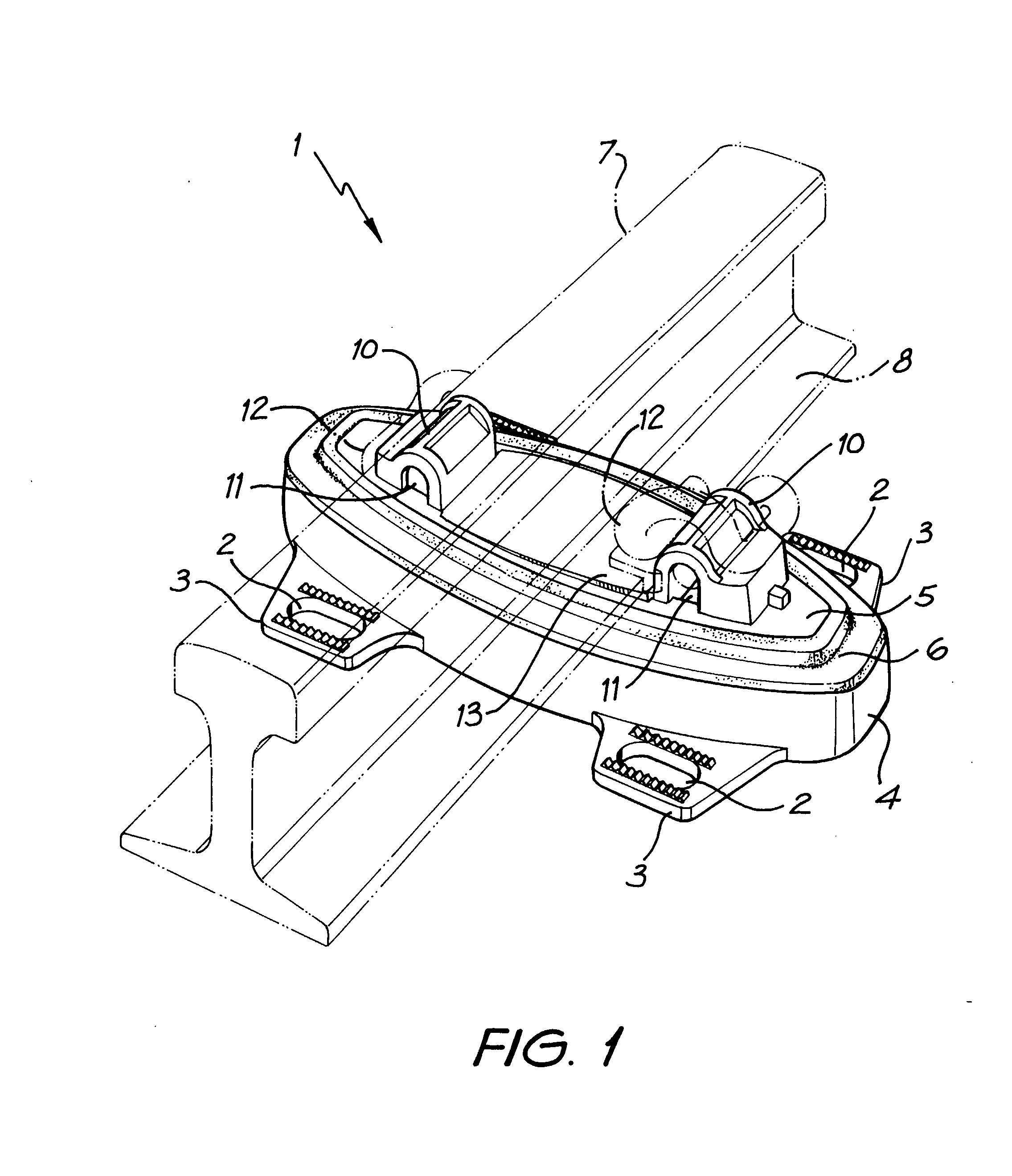
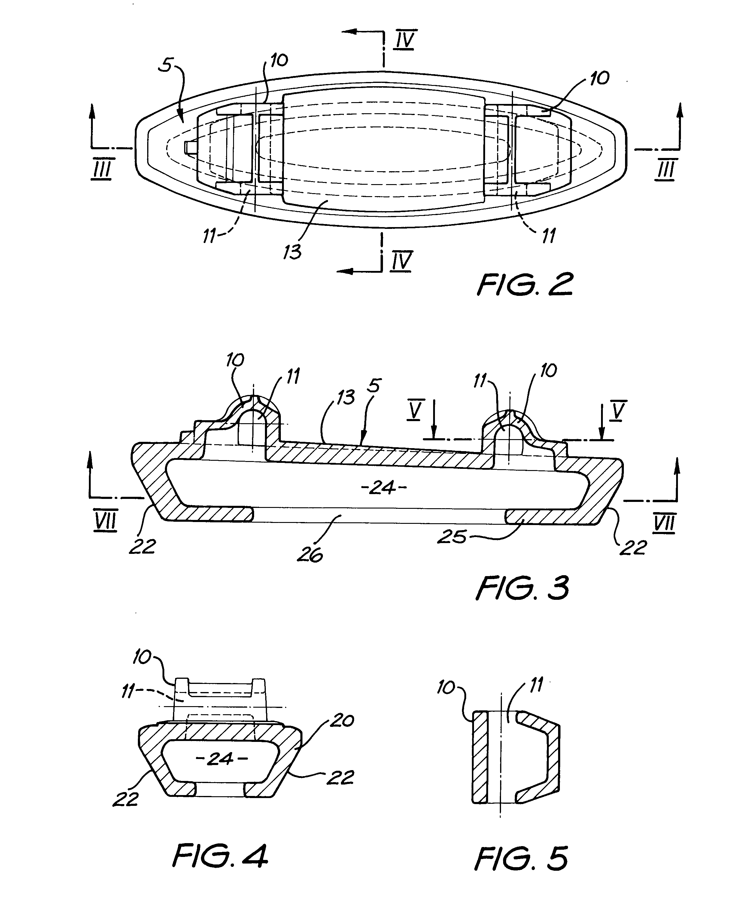
[0021]The assembly 1 shown in FIG. 1 is attached to a track foundation by screw spikes (not shown) driven downwardly through apertures 2 in four anchor lugs 3 arranged in pairs at each side of a bottom plate 4 of the assembly. The plate 4 is made from cast iron. A cast iron top plate 5 is mounted centrally in an opening in the upper surface of the bottom plate 4 and is held in place by a thick layer 6 of an elastomeric material such as rubber, sandwiched between opposed and spaced frusto-conical surfaces provided respectively on the two plates 4 and 5. The frusto-conical surface 5 tapers downwardly. The layer 6 is vulcanised to both plates 4 and 5.

[0022]A track rail 7, shown diagrammatically in broken outline, has a bottom flange 8 that locates between two spaced clip mounts 10 projecting upwards from the top plate 5 and cast integrally with it. Each mount 10 is formed with a horizontal and open-ended socket 11 for the reception of one end-portion of a resilient steel rail holding c...


PUM

PropertyMeasurementUnit
thicknessaaaaaaaaaa
weightaaaaaaaaaa
thickaaaaaaaaaa

Abstract

A top plate for an elastomeric rail fastening assembly has a downwardly tapering lower wall terminating in an inwardly-directed lip defining a mouth leading into a well. The cavity of the well extends upwardly to provide the interiors of rail-holding mounts between which a bottom flange of a rail may be located. The mounts have open-ended sockets for receiving spring clips used to hold the rail in position between the mounts, and the sockets and well communicate with one another. This form of top plate allows less metal to be used for its construction, requires less dressing after casting, and precisely locates the sockets with respect to one another.

Description

FIELD OF THE INVENTION[0001]THIS INVENTION relates to castings and is more specifically, although not exclusively, concerned with the construction of a metal casting used to provide a top plate of an elastomeric rail fastening assembly used to secure rails to the underlying bed of a railway track.STATE OF THE ART[0002]Elastomeric rail fastening assembles are being used increasingly in situations where, for example, track noise and vibration caused by train wheels travelling along the rails, are to be lessened. Such an assembly comprises a top plate attached by clips to the under-flanges of the rail, a bottom plate which is securely attached to the track bed to hold the assembly in place, and a layer of an elastomeric material such as rubber usually sandwiched between frusto-conical and spaced opposed surfaces of the top plate and the bottom plate.[0003]The top plate is conventionally formed by an iron casting having a central well formed in its undersurface to assist retention of th...

Claims


Application Information

Patent Timeline
Patent Type & Authority Applications(United States)
IPC IPC(8): B22D25/00B22C9/00B22C9/22B22C9/24B22D25/02E01B3/24E01B9/34E01B9/42E01B9/48E01B9/60E01B9/62
CPCE01B3/24E01B9/40E01B9/34E01B9/38B22D15/00E01B9/44
Inventor SCHONSTEIN, PETER J.
Owner DELKOR RAIL
Learn More