
Suspension for a pressure sensitive touch display or panel

a touch display or panel, pressure sensitive technology, applied in the direction of washstands, lighting support devices, instruments, etc., can solve the problems of poor production yield, dead spots, and further reduced clarity, and achieve cost-effective effects

Inactive Publication Date: 2010-05-27
F-ORIGIN
View PDF10 Cites 39 Cited by
  • Summary
  • Abstract
  • Description
  • Claims
  • Application Information

AI Technical Summary

Benefits of technology

[0018]It is, therefore, an object of the present innovation to allow for cost efficient design and manufacturing of force sensing sensor-based touch screen products of different sizes, designs and applications with one and the same conceptual component.
[0019]It is another object to provide a suspension solution that can be implemented and assembled at a low cost, and yet support different sensor types and sizes without any conceptual changes and a minimum of component changes.
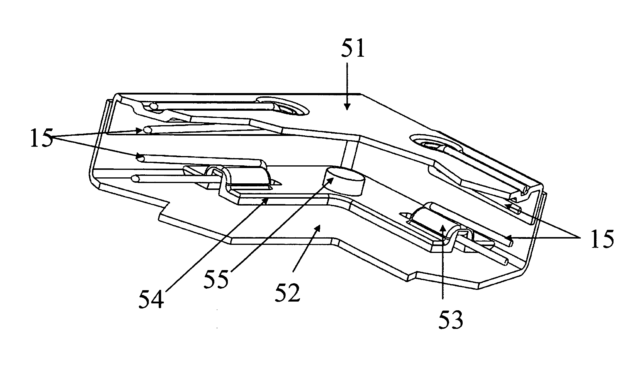
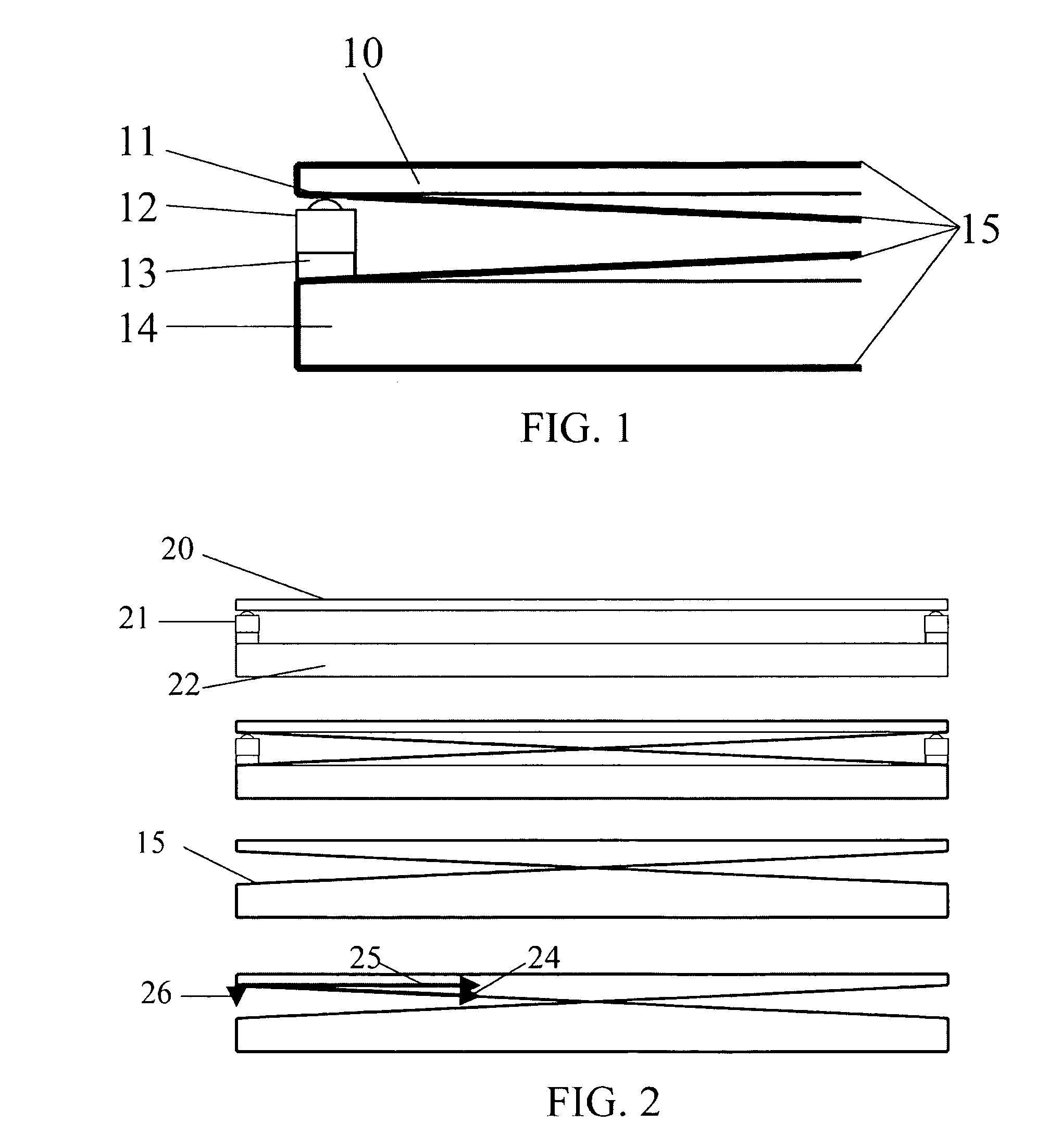
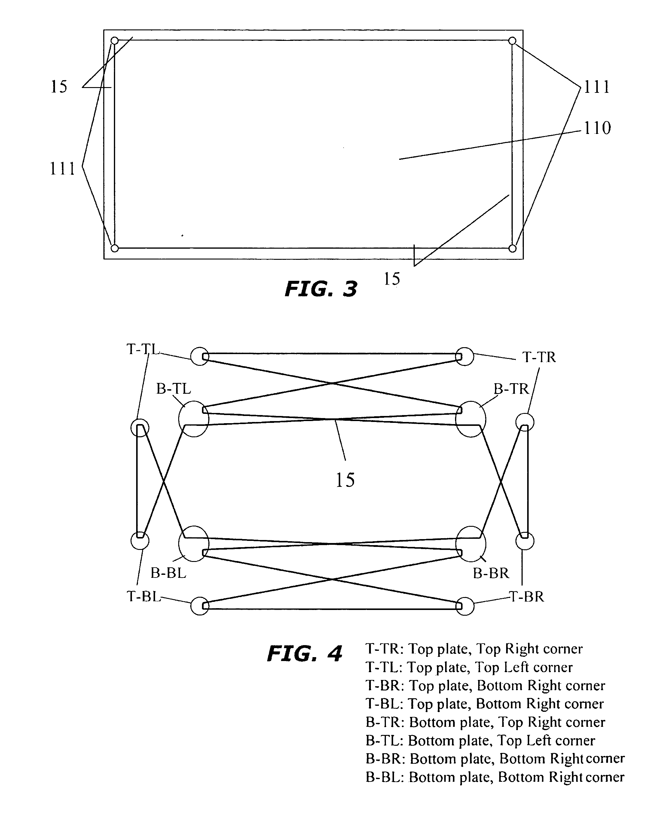
[0020]These and other objects are accomplished by a mechanical suspension platform for sensor-based touch screen products that uses a suspension elbow component. The elbow component, for example, is formed with a 90 degree angled-V with diverging legs. The two legs of the V are shaped with mechanical loops that allow for the suspension line or cable to be inserted and wrapped around. The suspension line can now be placed so that one end pulls the touch plate towards the bottom plate and the other end pulls the elbow component along the side of the top (or bottom plate) at a diagonal. With one elbow component in each corner of the touch plate, the plate can be strung with the suspension line to create an optimal suspension method for the force based touch screen system. If needed, the same elbow component or similar component can also be used for the bottom plate. The elbow component allows a simple and fast connection to the touch (or back) plane by glue or similar strong adhesive.
[0021]By shaping the component into a 90 degree angle-V, the elbow component can be placed at each corner without adding much space for the actual suspension string, which typically runs right outside the four sides of the display module in a force based touch screen. In addition, the elbow component can extend and wrap around the edge of the touch plane component in order to provide a larger area for adhesive and to provide self adjusting component placement.

Problems solved by technology

The disadvantage of a resistive pad is that the resistive membrane material will wear out, initially resulting in further reduced clarity followed by dead spots.
In addition, the production yield is typically rather poor and the technology has a few disadvantages such as a fixed (non-user adjustable) actuation force and the light throughput through the resistive membranes is typically only around 70% to 75%.
Capacitive pads are relatively expensive to manufacture compared to resistive, and can only detect objects with sufficient capacitance.
Small objects, such as the end of a regular stylus or pen, do not have enough capacitance to ground or transcapacitance to be detected by a capacitive touchpad.
This often leads to difficulties in implementing certain end-user features, such as handwriting recognition.
These devices work well, but are generally much too expensive for general applications.
Infra red light based displays work in a similar fashion, but this technology typically adds a large size and price.
The market success for force based touch screens and pads has so far been very limited for various reasons.
Such translational movement creates uncontrolled friction or forces, and tends to distort the sensor readings.
Although the Brown et al. suspension system can be manufactured at a low cost both in terms of material as well as assembly costs, there are significant constraints involved in the product implementation.
Both approaches provide suitable functionally but require costly drilling of holes in glass or smoothing / rounding of glass edges.
This adds significant manufacturing cost to the overall structure.
In addition, the resulting suspension line on the top side of the glass plate complicates mechanical add-on items, such as water seals.
Another mechanical problem is the placement of sensors and support for multiple sensor types.

Method used


Image

  • Suspension for a pressure sensitive touch display or panel
  • Suspension for a pressure sensitive touch display or panel
  • Suspension for a pressure sensitive touch display or panel

Examples


Embodiment Construction

[0038]The present invention is a suspension platform for a touch sensitive input panel or display especially suited for use in cellular phones and personal digital assistants (PDAs), PC Tablets, as well as laptops, PCs, office equipment, medical equipment, TV Monitors, or any other device that uses touch sensitive displays or panels.

[0039]The suspension platform presumes the use of a force sensor-based touch screen implementation, such as the technology disclosed in existing patent filings and publications such as U.S. application 2008003374 for “integrated Feature for Frictionless Movement of Force Sensitive Touch Screen, filed Mar. 14, 2008 by Brown et. al., and U.S. patent application Ser. No. 12 / 009,964 for “Integrated Force Sensitive Lens and Software”, filed 23 Jan. 2008 by Mölne et. al.

[0040]As is described in these patents, it is known to use a plurality (e.g., four) force sensors to locate a touch point on a touch screen or touch pad. However, prior mechanical implementatio...


PUM


Abstract

A mechanical suspension platform for sensor-based touch screen products that uses a suspension bracket with one or more suspension line channels that allow for a suspension line or cable to be inserted and wrapped around. The suspension brackets allow the suspension line to be strung so that one end pulls the touch plate towards the bottom plate and the other pulls along a diagonal. With one suspension bracket in each corner of the touch plate, the plate can be strung with the suspension line to create an optimal suspension for a force-based touch screen system.

Description

CROSS-REFERENCE TO RELATED APPLICATION(S)[0001]The present application derives priority from U.S. provisional application Ser. No. 61 / 198,536 filed Nov. 6, 2008, and is a continuation-in-part of U.S. patent application Ser. No. 12 / 009,964 for “Integrated Force Sensitive Lens and Software”, filed 23 Jan. 2008 by Mölne et. al.BACKGROUND OF THE INVENTION[0002]1. Field of the Invention[0003]The present invention relates generally to input devices for electronics and, more particularly, to a suspension for a touch sensitive input panel or display especially suited for use in cellular phones and personal digital assistants (PDAs), PC Tablets, as well as laptops, PCs, office equipment, medical equipment, TVs Monitors, or any other device that uses touch sensitive displays or panels.[0004]2. Description of the Background[0005]Touch sensitive screens can detect the application of fingers and other passive objects. Touch screens are gaining in popularity and have been deployed in many product...

Claims


Application Information

Patent Timeline
IPC IPC(8): F16M13/02
CPCG06F3/0418G06F3/0414
Inventor SMITH, GARY
Owner F-ORIGIN
Learn More