Scintillator array and a method of constructing the same

a scintillator array and array technology, applied in the field of ionizing radiation imaging sensors, can solve the problems of reducing spatial sensitivity, deteriorating fold image effect, and light traveling, and achieve the effect of improving scintillator arrays

Inactive Publication Date: 2010-05-27
CMT - MEDICAL TECHNOLGIES
View PDF14 Cites 52 Cited by
  • Summary
  • Abstract
  • Description
  • Claims
  • Application Information

AI Technical Summary

Benefits of technology

[0014]It is an object of the present invention to provide a physical structure of improved scintillator arrays.

Problems solved by technology

The disadvantage of both is that, in the case of a scintillator, light can travel to a photodiode that is not the one closest to its origin.
This light dissipation leads to two-fold image deterioration effect: (a) drop in spatial sensitivity (i.e. blurring), and (b) lower light intensity collectable per pixel per X-ray photon.
The fabrication methods used for making these scintillators arrays are optimal for this size of elements and are not suitable for constructing arrays of substantially smaller elements.
However, light spread cannot be totally avoided for thicker CsI plate, thus limiting the thickness of the plate or the achievable resolution.
Moreover, the problem of fabricating relatively small scintillators units remains unsolved in the description.

Method used


Image

  • Scintillator array and a method of constructing the same
  • Scintillator array and a method of constructing the same
  • Scintillator array and a method of constructing the same

Examples


Embodiment Construction

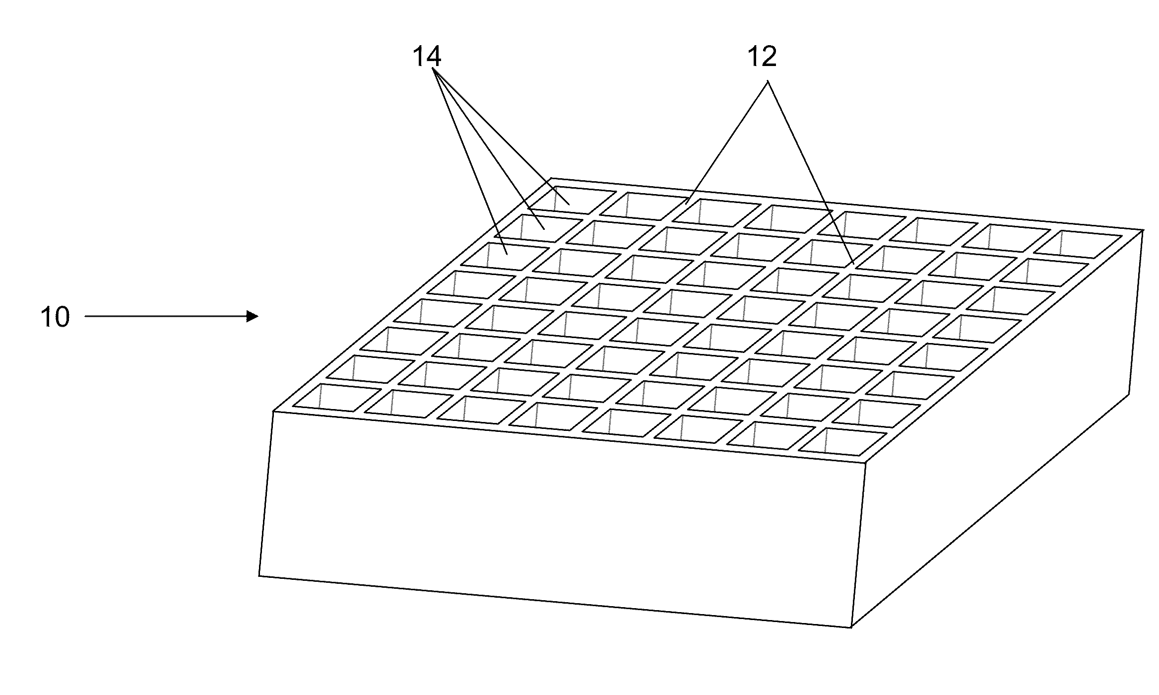
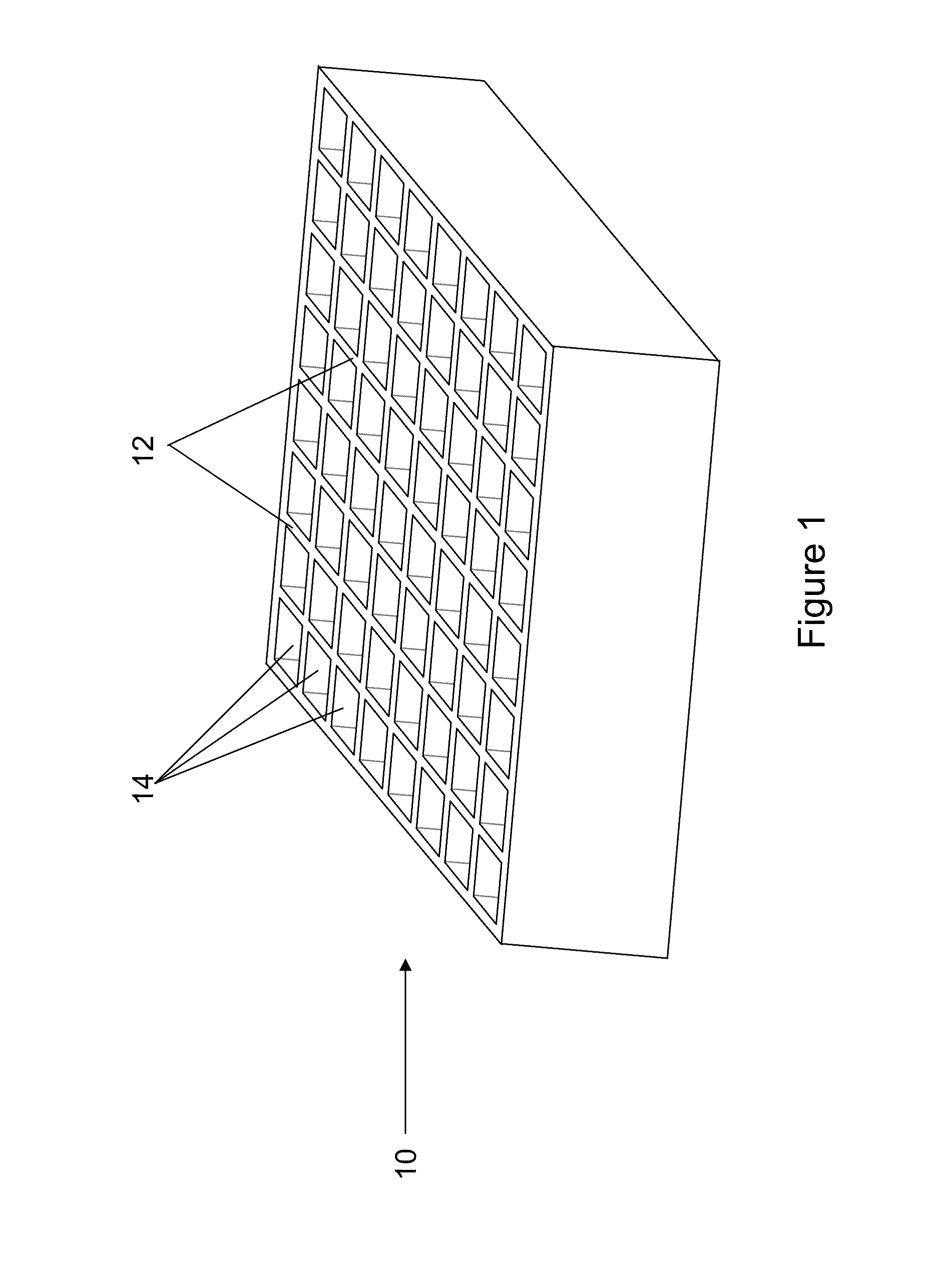
[0076]The present invention provides a new method for manufacturing a pixelated scintillator at a high pitch and a high fill factor, stopping power, and efficiency.

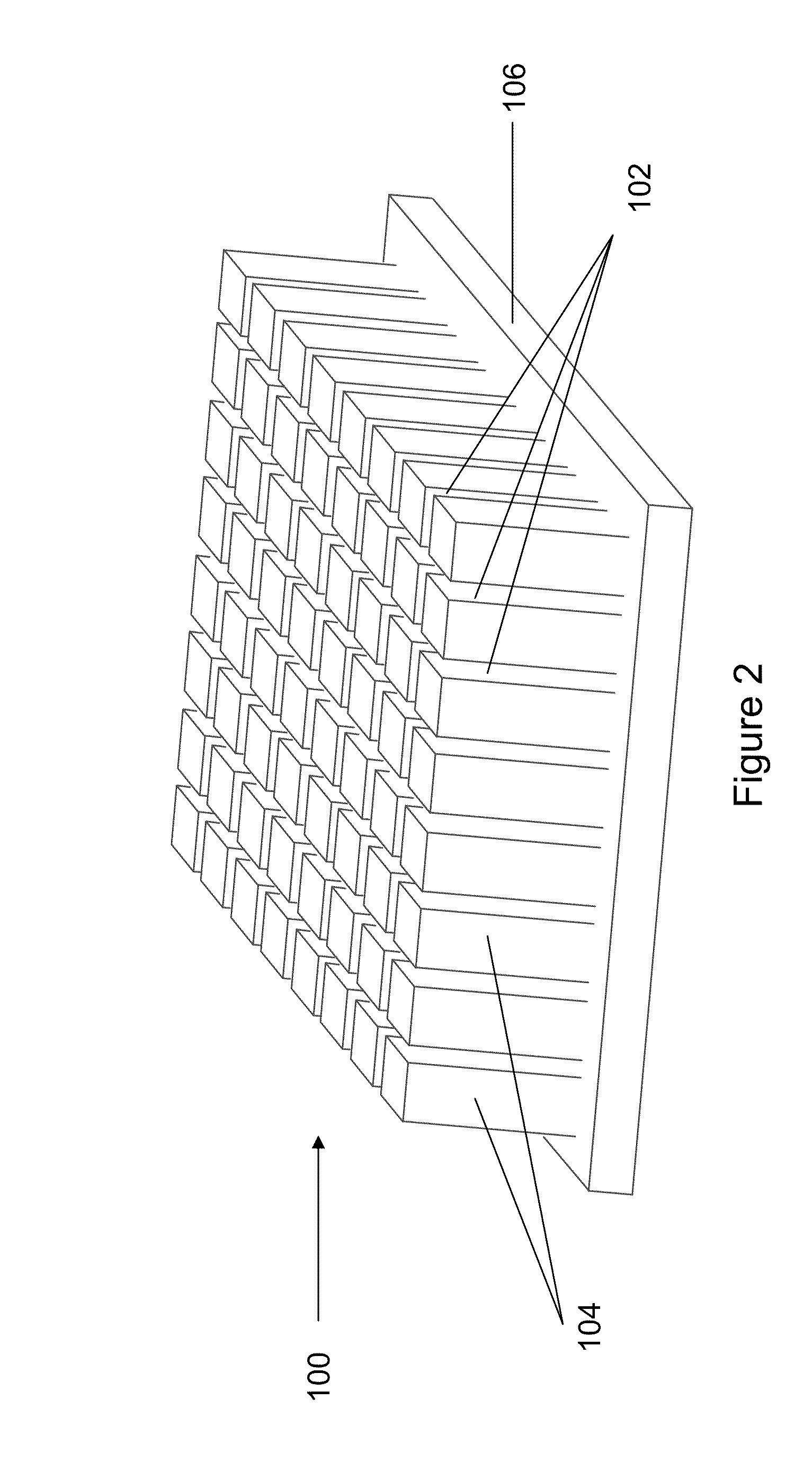
[0077]The present invention provides means of optimizing the method for maximal light output and minimal dissipation of light between adjacent pixels.

[0078]In addition, it is provided means of using this approach to provide improved scatter-radiation rejection at the detector entrance, as either an integral part of the scintillator or an additional assembly.

[0079]A pixelated scintillator is necessary for both improving spatial imaging resolution and increasing light output per pixel. And yet, pixelated scintillators and methods for producing them are available for pixel sizes that are inadequate for high resolution X-ray imaging. For example, scintillator pixels used in Computed Tomography (CT) are typically 1 mm in size. The methods for making such pixels are not suitable for higher resolution imaging, since the relative...


PUM


Abstract

A pixilated scintillator, scintillator array and methods of fabricating the same are provided. The scintillator array comprises a grid having walls, a scintillator crystal packed between the walls, and a reflective coating provided between the walls and the scintillator crystal.

Description

FIELD OF THE INVENTION[0001]The present invention relates to ionizing radiation imaging sensor. More particularly, the present invention relates to a sensor array such as a scintillator and a method of constructing the same.BACKGROUND OF THE INVENTION[0002]Imaging of the human body in medical applications is often achieved by detection of X-rays in sensor materials. A sensor material is a material which, when interacting with X-ray photons, undergoes a physical change that is measurable by dedicated acquisition electronics. The combination of a sensor material and the corresponding acquisition electronics defines an X-ray detector or imager.[0003]In a substantially direct-conversion X-ray detector, the sensor material converts X-ray energy to electrical charge, which is further processed by electronics processors. In a substantially indirect-conversion X-ray detector, the sensor material produces light, this is later converted to electrical charge.[0004]The sensor materials used in ...

Claims


Application Information

Patent Timeline
Patent Type & Authority Applications(United States)
IPC IPC(8): G01T1/202H01L31/18
CPCH01L27/14663G01T1/1644G01T1/2002
Inventor LIFSHITZ, RONENBOLAN, ADI
Owner CMT - MEDICAL TECHNOLGIES
Why Eureka
Try Eureka