Systems And Methods Of High Resolution Three-Dimensional Imaging

a three-dimensional imaging and high-resolution technology, applied in the field of three-dimensional imaging systems and methods, can solve the problems of inability to obtain information about the distance (z) of an object from the fpa by itself, inability to detect color, and high speed, and achieve high resolution

Active Publication Date: 2010-05-27
NLIGHT INC
View PDF26 Cites 373 Cited by
  • Summary
  • Abstract
  • Description
  • Claims
  • Application Information

AI Technical Summary

Benefits of technology

[0012]The present invention provides systems and methods of high resolution three-dimensional imaging, including those having a wide field of view and adjustable depth of field. Specifically, the systems a

Problems solved by technology

However, most FPAs by their nature cannot detect color, only the presence and quantity of light.
Additionally, FPAs are limited to collecting information about light emanating from a scene in two dimensions, horizontal (x) and vertical (y), in front of the imaging device, often referred to as the field-of-view (FOV).
Most FPAs cannot, by themselves, obtain information about the distance (z) of an object from the FPA without the use of complex, high speed, expensive read-out circuits.
Both types of techniques typically are computational intensive, provide only limited information about the three dimensional features of a scene, and may be unsuitable for moving objects.
Additionally, stereoscopy typically requires precise knowledge of the relative position and angle at which the multiple two-dimensional images are obtained and so requires extensive calibration procedures and limited flexibility.
The multiple views also means that more lines of sight will be obscured.
This limits the use of such system in uncontrolled environments, can significantly increase the cost of any implementation, and limits the accuracy and precision of any calculated distance values.
As such, the maximum scanning speed may be limited by the amount of time required to make a measurement at each point, and the speed of the mirror o

Method used


Image

  • Systems And Methods Of High Resolution Three-Dimensional Imaging
  • Systems And Methods Of High Resolution Three-Dimensional Imaging
  • Systems And Methods Of High Resolution Three-Dimensional Imaging

Examples


Embodiment Construction

1. Overview

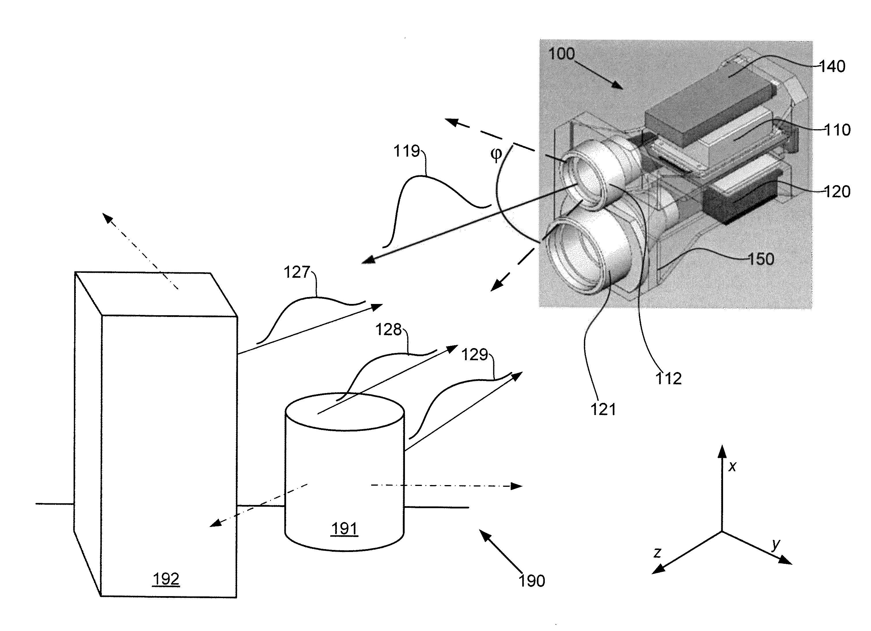
[0047]Embodiments of the invention provide systems and methods for obtaining high resolution images of scenes, including wide field of view scenes. Specifically, the systems and methods may simultaneously record three dimensional position information for multiple objects in a scene with high spatial and distance resolution, along with intensity (grey-scale or color) information about the scene. This information, both coordinate and intensity, is recorded for every pixel in an array of pixels for each image. The intensity and position information are combined into a single three-dimensional image that approximates a human view of the scene, and which further records the three-dimensional coordinates of the shape and relative position of each object in the scene. A series of such images may be acquired in similar fashion to a digital video camera, providing a “movie” of changes in the scene over time, each three-dimensional image in the movie being referred to as a frame. I...


PUM


Abstract

Embodiments of the invention provide systems and methods for three-dimensional imaging with wide field of view and precision timing. In accordance with one aspect, a three-dimensional imaging system includes an illumination subsystem configured to emit a light pulse with a divergence sufficient to irradiate a scene having a wide field of view. A sensor subsystem is configured to receive over a wide field of view portions of the light pulse reflected or scattered by the scene and including: a modulator configured to modulate as a function of time an intensity of the received light pulse portion to form modulated received light pulse portions; and means for generating a first image corresponding to the received light pulse portions and a second image corresponding to the modulated received light pulse portions. A processor subsystem is configured to obtain a three-dimensional image based on the first and second images.

Description

CROSS-REFERENCE TO RELATED APPLICATIONS[0001]This application claims the benefit of the following applications, the entire contents of each of which are incorporated by reference herein:[0002]U.S. Provisional Patent Application No. 61 / 117,788, filed Nov. 25, 2008 and entitled “Method and Apparatus for a 3D Digital Imaging Device;”[0003]U.S. Provisional Patent Application No. 61 / 121,096, filed Dec. 9, 2008 and entitled “Method and Apparatus for Wide Field of View Large Aperture, Low Voltage Optical Shutter;” and[0004]U.S. Provisional Patent Application No. 61 / 166,413, filed Apr. 20, 2009 and entitled “Method and Apparatus for Large Divergence Laser Illuminator.”FIELD OF THE INVENTION[0005]This application generally relates to systems and methods of three-dimensional imaging.BACKGROUND OF THE INVENTION[0006]Digital electronics have made it possible to record a grey scale or color image of a scene, as a still image, as a series of still images, or as a video. A video is a series of sti...

Claims


Application Information

Patent Timeline
IPC IPC(8): H04N13/02G01S7/486G01S7/4865G01S17/10G01S17/89G01S17/894
CPCG01S7/4816G01S17/89H04N13/0207G01S7/4865G01S17/10G01S7/484G01S7/486H04N13/0253H04N13/204H04N13/207H04N13/254H04N13/296G01S17/894
Inventor BANKS, PAUL S.
Owner NLIGHT INC
Why Eureka
Try Eureka