Plug-in unit

a plug-in unit and plug-in technology, applied in the direction of protective switch terminal/connection, laminated bus-bars, switch terminals/connections, etc., can solve the problems of wiring failure, complicated installation of such devices, and so as to increase the number of assembly processes

Active Publication Date: 2010-05-27
TOKYO ELECTRON LTD
View PDF6 Cites 23 Cited by
  • Summary
  • Abstract
  • Description
  • Claims
  • Application Information

AI Technical Summary

Benefits of technology

[0009]However, in Patent Documents 1, 2 and 3, a screw member is used to fix a branch breaker to a distribution...

Problems solved by technology

However, in Patent Documents 1, 2 and 3, a screw member is used to fix a branch breaker to a distribution panel, so that installation thereof may be complicated and the nu...

Method used


Image

  • Plug-in unit
  • Plug-in unit
  • Plug-in unit

Examples


case 22b

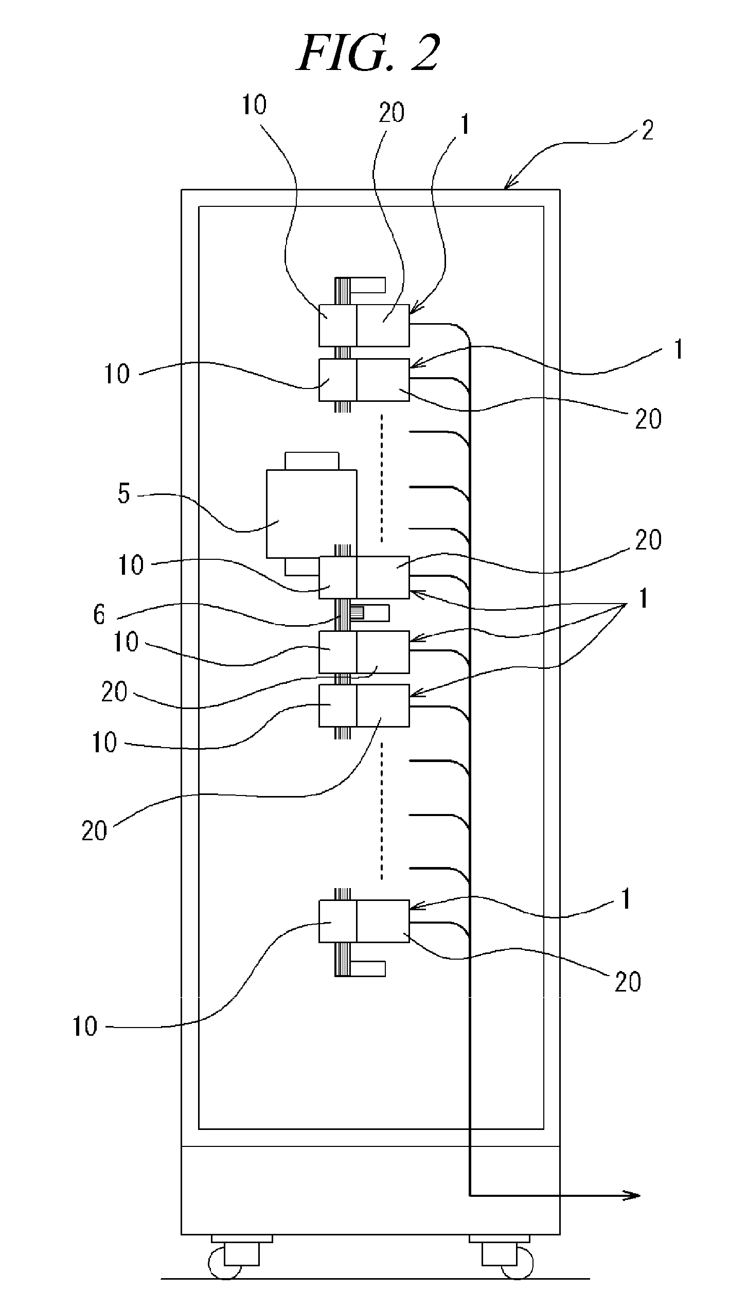
[0045]Further, a rectangular case 22b protrudes from the joint surface 21 of the electric device 20 to surround and protect the plug terminal 22. The case 22b is configured to be detachably fitted and inserted into the recess 16 which receives the plug-in terminal metal fitting 30 of the breaker 10. When the breaker 10 is joined with the electric device 20, the case 22b is fitted and inserted into the terminal metal fitting receiving recess 16, whereby the breaker 10 is firmly joined with the electric device 20.

[0046]In this case, the plug terminal 22 is installed at one contact point 24b of output contact points 24b and 24c electrically connected with a movable contact point 24a which is operated by exciting an electric coil 23 through electric conduction. The electric coil 23 is installed horizontally in the electric device 20. The other contact point 24c is connected with a plug-in terminal metal fitting 30B installed at a rear part of the electric device 20. The plug-in terminal...

fourth embodiment

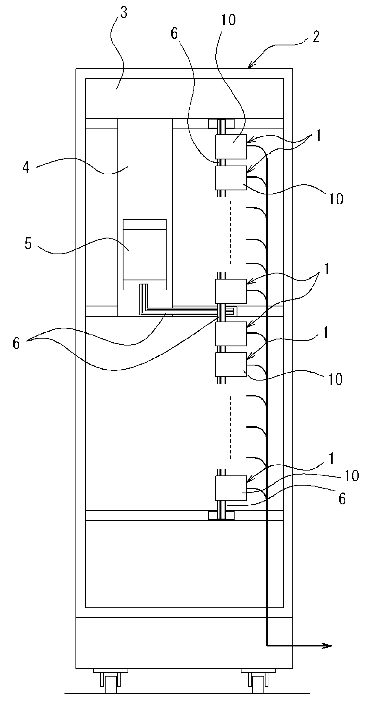
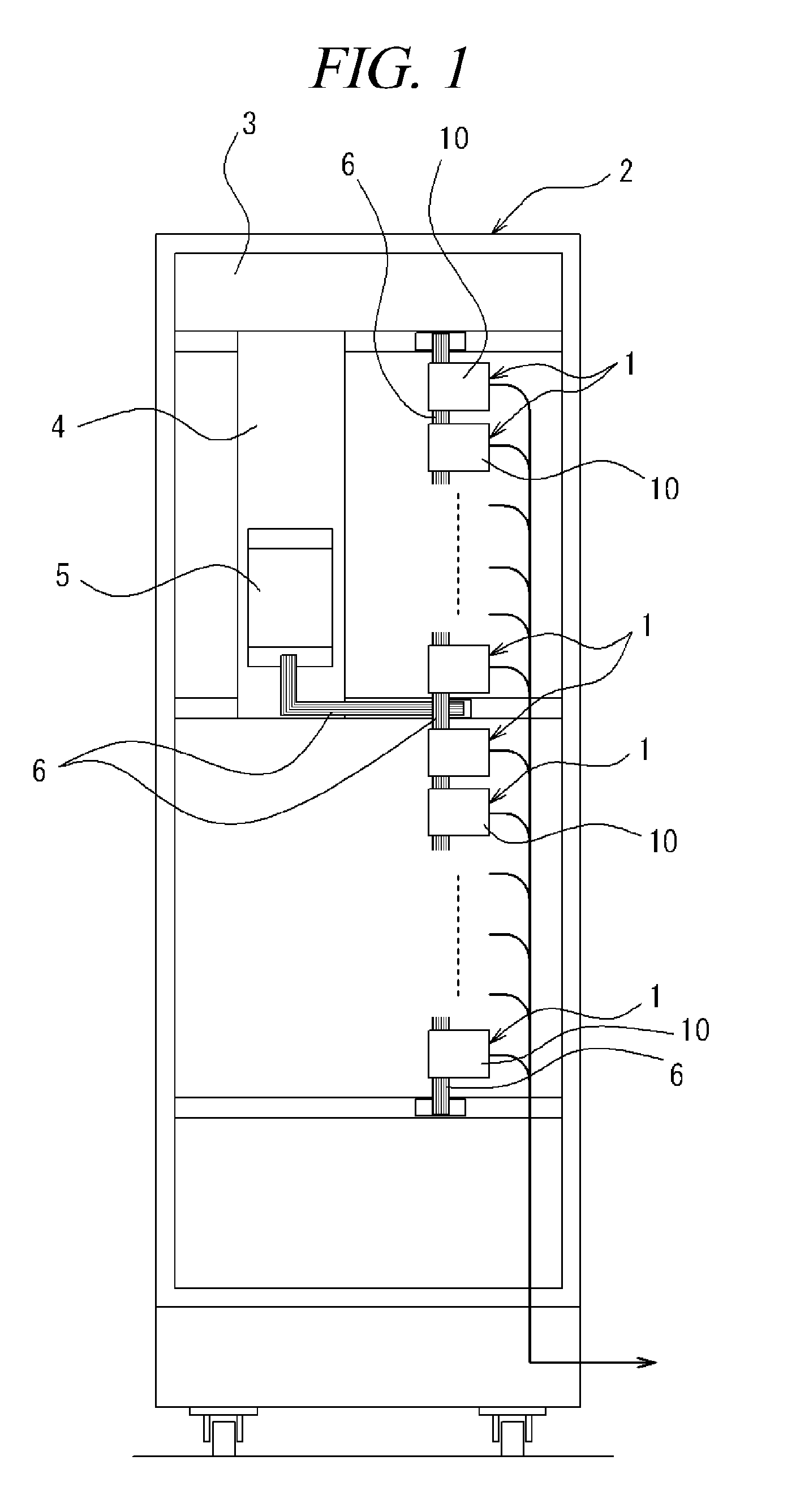
[0080] configured as stated above, the busbars 6 may be connected to one of the joint surface 13 and the top surface 80 of the breaker 10 or may be connected to both the joint surface 13 and the top surface 80, whichever is necessary. When the busbars 6 are connected to the joint surface 13 of the breaker 10, the busbars 6, which are connected with the terminal metal fittings installed in the plurality of recess grooves 14 provided at the joint surface 13 of the breaker 10, can be maintained in parallel to each other by the holding member 15, so that the busbars 6 can be prevented from being disjoined. Further, when the busbars 6 are connected to the top surface of the breaker 10, the busbars 6 can be connected with the breaker 10 after the breaker 10 is joined with the electric device 20.

[0081]The plug-in unit of the present disclosure is configured as explained above and the following effects can be achieved.

[0082](1) In accordance with the present disclosure, a joint surface of a...


PUM


Abstract

A plug-in unit includes a breaker electrically connected with a busbar at a power supply side and an electric device electrically connected with the breaker. Joint surfaces making contact with each other are formed at the breaker and the electric device, respectively. The breaker includes a terminal metal fitting connecting the busbar thereto and a plug-in terminal metal fitting installed at the joint surface of the breaker, and the electric device includes a plug terminal, which is installed at the joint surface thereof and capable of being connected with the plug-in terminal metal fitting. The breaker is detachably joined with the electric device by an engaging member including an engaging unit and an engagement receiving unit. The engaging unit and the engagement receiving unit are installed at the joint surfaces of the breaker and the electric device, respectively, and detachably engaged with each other.

Description

CROSS-REFERENCE TO RELATED APPLICATION[0001]This application claims the benefit of Japanese Patent Application No. 2008-301887, filed on Nov. 27, 2008 and Japanese Patent Application No. 2009-106202, filed on Apr. 24, 2009, the entire disclosures of which are incorporated herein by reference.FIELD OF THE INVENTION[0002]The present disclosure relates to a plug-in unit.BACKGROUND OF THE INVENTION[0003]Generally, a distribution panel has a structure in which a plurality of busbars, which is electrically connected with a load terminal of, e.g., a three-phase 200V main breaker connected with a power supply, is connected with a power supply terminal of a branch breaker, so that electricity of, e.g., a single-phase 200V power is supplied to an electric device such as a magnet conductor serving as a load.[0004]Conventionally, there has been known a configuration of a distribution panel in which a branch breaker having a plug terminal metal fitting capable of electrically connecting with bus...

Claims


Application Information

Patent Timeline
IPC IPC(8): H02B1/04
CPCH01H1/5844H01H1/5866H01H71/0271H01H89/06H01H71/08H01H71/082H01H71/04H02B1/20H02B1/205H02G5/005H01R9/24H01H73/20H02B1/40
Inventor ICHINOMIYA, KENJIKAWANO, TOSHIYUKISATOH, TAKAMI
Owner TOKYO ELECTRON LTD
Why Eureka
Try Eureka