Lap-fillet arc welding joint and joint structure for press forming parts

a technology of arc welding and arc welding, which is applied in the direction of manufacturing tools, vehicle sub-unit features, and cellulosic plastic layered products, etc., can solve the problems of ineffective welding joint function and insufficient reduction of fatigue cracks, so as to increase welding cost and process number, the effect of improving fatigue strength

Active Publication Date: 2018-11-29
JFE STEEL CORP
View PDF0 Cites 0 Cited by
  • Summary
  • Abstract
  • Description
  • Claims
  • Application Information

AI Technical Summary

Benefits of technology

[0013]With the lap-fillet arc welding joint and the joint structure for press forming parts according to an aspect of the present invention, a weld bead is formed on an end portion of one sheet of overlapped two sheets and a surface of the other sheet along the end portion, the other sheet has a projecting portion projecting from the surface at a side of a weld toe of at least one of a start portion and a termination portion of the weld bead, and the weld toe is located on a slope surface portion of the projecting portion at the side of the end portion of the one sheet. With this configuration, stress concentration is moderated when load repeatedly acts on the weld toe, and fatigue strength is improved without increasing welding cost and the number of processes.

Problems solved by technology

For this reason, the technique cannot necessarily reduce generation of fatigue cracks sufficiently.
The technique disclosed in Patent Literature 1 thus does not function as an effective method for a welding joint in which stress concentration is generated at the highest level in the start portion and the termination portion of the weld bead and a joint structural member provided by joining parts by the welding joint.

Method used


Image

  • Lap-fillet arc welding joint and joint structure for press forming parts
  • Lap-fillet arc welding joint and joint structure for press forming parts
  • Lap-fillet arc welding joint and joint structure for press forming parts

Examples


Embodiment Construction

[0026]Hereinafter, a lap-fillet arc welding joint and a joint structure for press forming parts according to an embodiment of the present invention will be described with reference to the drawings.

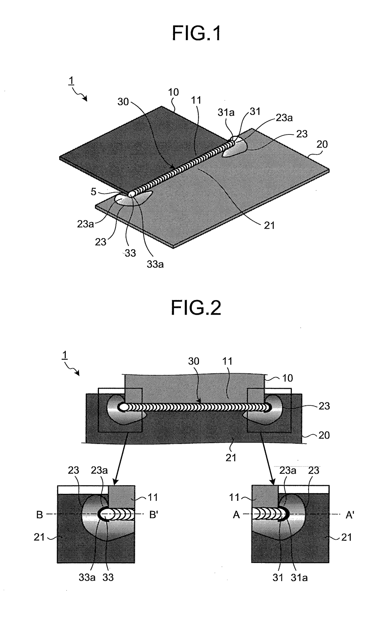
[0027]FIG. 1 is a perspective view of the lap-fillet arc welding joint in the embodiment of the present invention. As illustrated in FIG. 1, a lap-fillet arc welding joint 1 in the embodiment of the present invention is provided by overlapping one sheet (upper sheet 10) and the other sheet (lower sheet 20) with an overlap margin portion 5 and joining them using arc welding so as to form a weld bead 30 on an end portion 11 of the upper sheet 10 and a surface 21 of the lower sheet 20 along the end portion 11.

[0028]FIG. 2 is a top view of the lap-fillet arc welding joint 1. The weld bead 30 is formed by advancement of welding to the left side from the right side in FIG. 2 and a weld toe 31a is formed in a start portion 31 of the weld bead 30 and a weld toe 33a is formed in a termination porti...


PUM

PropertyMeasurementUnit
stress concentrationaaaaaaaaaa
stress concentration factoraaaaaaaaaa
sheet thicknessaaaaaaaaaa

Abstract

A lap-fillet arc welding joint includes a weld bead, the weld bead being formed on an end portion of one sheet of overlapped two sheets and a surface of other sheet along the end portion. The other sheet includes a projecting portion projecting from the surface at a side of a weld toe of at least one of a start portion and a termination portion of the weld bead. The weld toe is located on a slope surface portion of the projecting portion at a side of the end portion of the one sheet.

Description

CROSS REFERENCE TO RELATED APPLICATIONS[0001]This is the U.S. National Phase application of PCT / JP2016 / 073230, filed Aug. 8, 2016, which claims priority to Japanese Patent Application No. 2015-209711, filed Oct. 26, 2015 and Japanese Patent Application No. 2016-094433, filed May 10, 2016, the disclosures of these applications being incorporated herein by reference in their entireties for all purposes.TECHNICAL FIELD OF THE INVENTION[0002]The present invention relates to a lap-fillet arc welding joint of a thin-walled welded structural member such as automotive parts and a joint structure for press forming parts.BACKGROUND OF THE INVENTION[0003]In recent years, weight reduction of automotive bodies has been desired from the viewpoint of prevention of global warming in the automotive industry. For example, application of a high-strength steel sheet to chassis frame parts and suspension arm parts can contribute to weight reduction of automotive vehicles by using a thin-walled steel she...

Claims


Application Information

Patent Timeline
Patent Type & Authority Applications(United States)
IPC IPC(8): B23K33/00B23K9/025
CPCB23K33/004B23K9/025B23K2101/006B23K2101/18B23K9/02B23K31/00B62D21/02B23K33/008B23K2101/28B23K33/00B60Y2410/124B32B15/01B32B15/04Y10T428/12493B32B23/042B32B15/00Y10T428/12
Inventor SHIOZAKI, TSUYOSHITOKITA, YUICHITAMAI, YOSHIKIYO
Owner JFE STEEL CORP
Why Eureka
Try Eureka