Hermetically sealed scroll compressor

a scroll compressor and hermetically sealed technology, which is applied in the direction of machines/engines, liquid fuel engines, positive displacement liquid engines, etc., can solve the problems of insufficient oil injection to the orbiting inner compression chamber, insufficient oil injection to the orbiting outer compression chamber, so as to reduce the volumetric efficiency and increase the internal compression power. , the effect of increasing the internal compression power

Active Publication Date: 2010-05-27
HITACHI JOHNSON CONTROLS AIR CONDITIONING INC
View PDF5 Cites 29 Cited by
  • Summary
  • Abstract
  • Description
  • Claims
  • Application Information

AI Technical Summary

Benefits of technology

[0031]According to the above hermetically sealed scroll compressor of the first mode of the present invention, suitable amounts of oil can be respectively supplied to the orbiting outer compression chamber and the orbiting inner compression chamber, and the internal leakage between the orbiting outer compression chamber and the orbiting inner compression chamber is reduced so that reduction in the volumetric efficiency and increase in the internal compression power can be suppressed.
[0032]Further, according to the above hermetically sealed scroll compressor of the second mode of the present invention, suitable amounts of oil can be respectively su

Problems solved by technology

In the scroll compressor of JP-Y2-1-17669 described above, the oil injection port at the center portion side is placed to communicate with the orbiting outer compression chamber in the state in which the wrap of the orbiting scroll is in contact with the outer side of the wrap of the fixed scroll, and therefore, there is the problem that supplying a proper amount of oil to both the orbiting outer compression chamber and the orbiting inner compression chamber is difficult.
For example, if a sufficient oil is set to be injected to the orbiting outer compression cha

Method used


Image

  • Hermetically sealed scroll compressor
  • Hermetically sealed scroll compressor
  • Hermetically sealed scroll compressor

Examples


first embodiment

[0056]A first embodiment of the present invention will be described by using FIGS. 1 to 16.

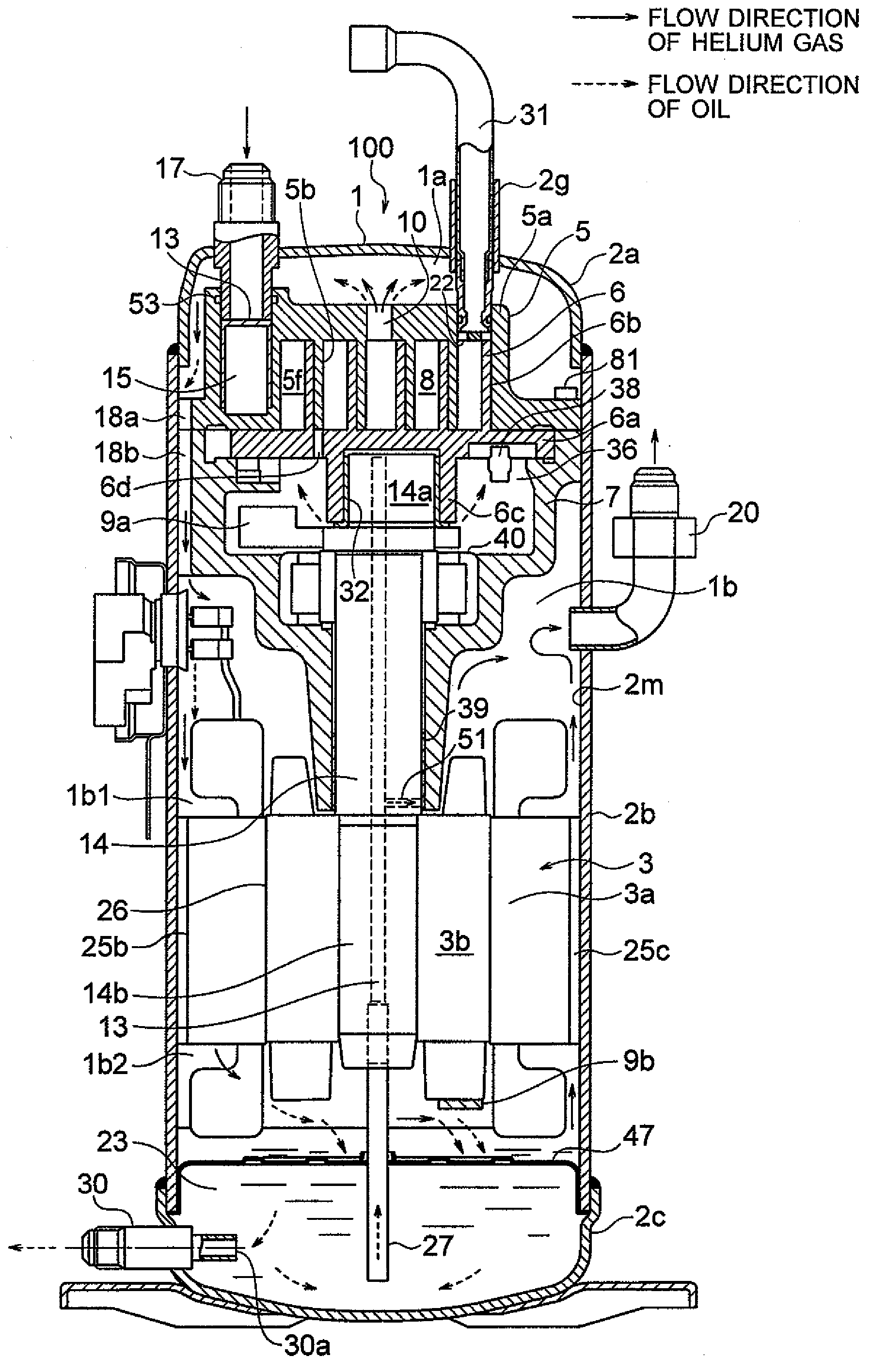
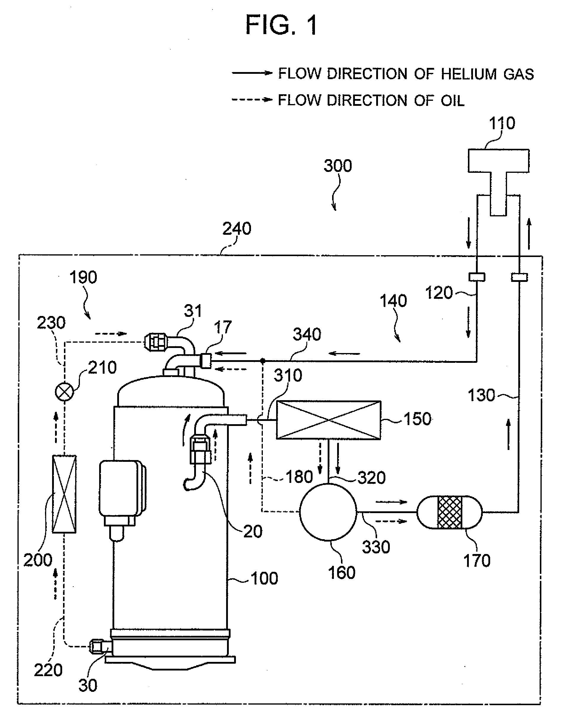
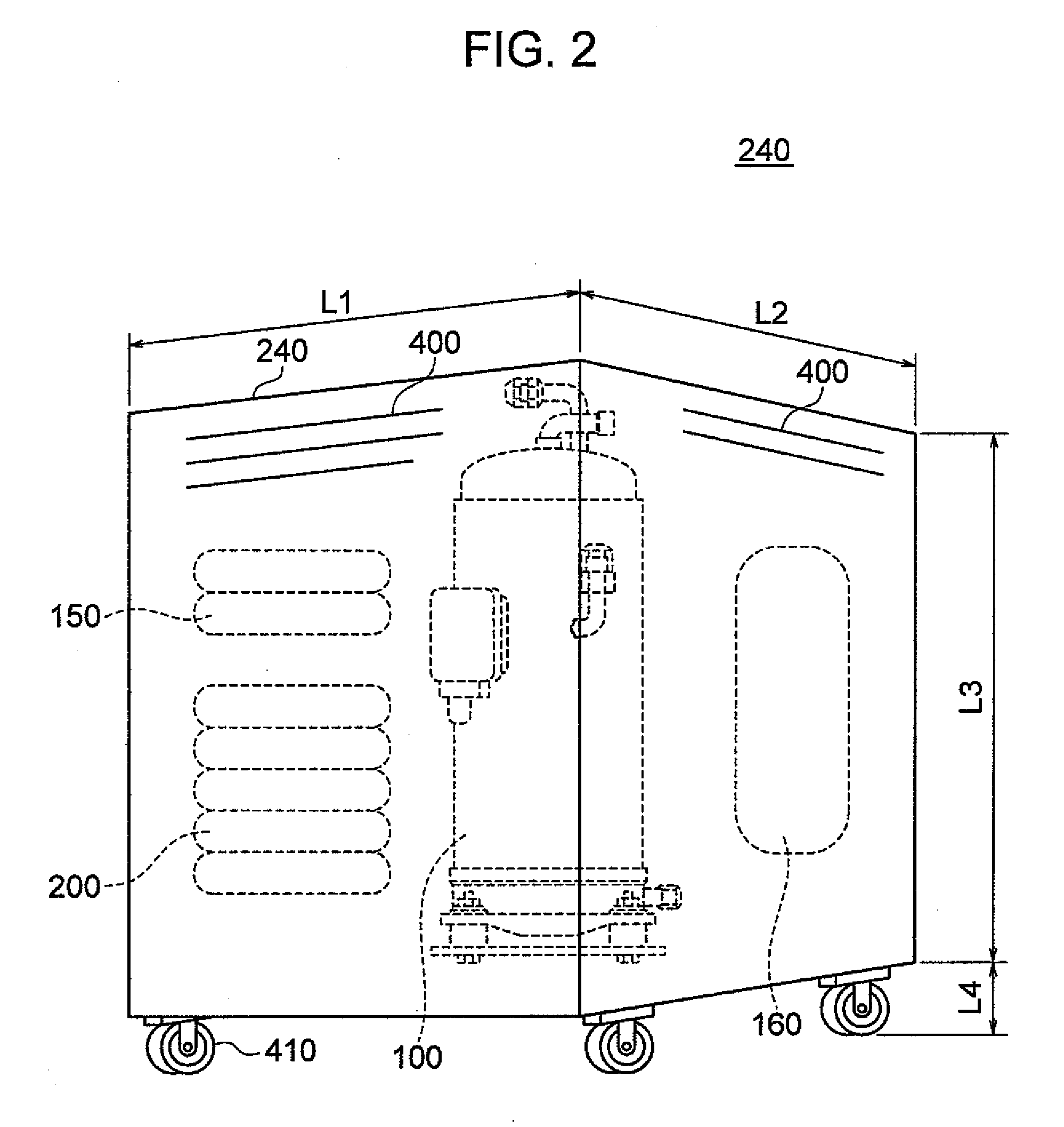
[0057]FIG. 1 is a general block diagram of a refrigerating apparatus including a hermetically sealed scroll compressor for helium of the present embodiment. FIG. 2 is a perspective view showing an appearance of a compressor unit of FIG. 1. FIG. 3 is a vertical sectional view of the hermetically sealed scroll compressor for helium of FIG. 1.

[0058]In FIG. 1, a refrigerating apparatus 300 is constituted by including a vertical type hermetically sealed scroll compressor 100 for helium (hereinafter, properly abbreviated as a compressor 100), and a refrigerator 110. The compressor 100 and the refrigerator 110 constitute a refrigeration cycle 140 which circulates an operating refrigerant by being connected through pipings 120 and 130. In the refrigeration cycle 140, a gas cooler 150, an oil separator 160, and an oil absorber 170 are placed. Further, a piping 180 for returning oil to the compressor 10...

second embodiment

[0139]Next, a second embodiment of the present invention will be described by using FIG. 17. FIG. 17 is a plane view of a fixed scroll of a hermetically sealed scroll compressor of the second embodiment of the present invention. The second embodiment differs from the first embodiment in the point which will be described as follows, and the other points are basically the same as in the first embodiment. Therefore, the redundant description will be omitted.

[0140]In the second embodiment, the positions of the oil injecting ports 22a and 22b are set near to the inlet pressure side from the positions of the oil injecting ports 22a and 22b of the first embodiment. In concrete, the opening positions of the oil injecting ports 22a and 22b are sifted to the positions near to the inlet chamber 5f side by about π / 6 to π / 4 rad with respect to first embodiment. The amount of substantially the wrap tooth thickness t is taken into consideration in the amount of the shifted angle. By shifting the o...

third embodiment

[0141]Next, a third embodiment of the present invention will be described by using FIGS. 18 and 19. FIG. 18 is a plane view of a fixed scroll of a hermetically sealed scroll compressor of the third embodiment of the present invention. FIG. 19 is a diagram explaining the relationship of the pressures inside the operation chambers of the orbiting outer compression chamber and the orbiting inner compression chamber, and the crankshaft rotational angle in the hermetically sealed scroll compressor of the third embodiment. The third embodiment differs from the first embodiment in the point which will be described as follows, and is basically the same as the first embodiment in the other points. Therefore, the redundant description will be omitted.

[0142]In the third embodiment, in the wrap shape without extending the terminal end portion of the fixed scroll inner curve, the injection mechanism portion of the first embodiment is applied. More specifically, the oil injecting port 22a to the ...


PUM


Abstract

In the hermetically sealed scroll compressor, an injection pipe for injecting a fluid to a compression chamber is connected to an injecting port of a fixed scroll. The injecting port includes a first injecting port which is provided in the vicinity of a fixed scroll inner curve and injects the fluid to an orbiting outer compression chamber, and a second injecting port 22b which is provided in the vicinity of a fixed scroll outer curve and injects the fluid to a orbiting inner compression chamber 8b. The second injecting port is placed in parallel in a radius direction with respect to the first injecting port and is placed so that an orbiting scroll wrap does not practically communicate with the orbiting outer compression chamber in the state in which the orbiting scroll wrap is in contact with the outer side of a fixed scroll wrap.

Description

BACKGROUND OF THE INVENTION[0001]The present invention relates to a hermetically sealed scroll compressor, and is particularly preferable for a hermetically sealed scroll compressor for refrigeration / air conditioning and for helium.[0002]As a conventional scroll compressor, there is the scroll compressor for compressing a gas such as air and a refrigerant, which is disclosed in JP-Y2-1-17669. The scroll compressor of JP-Y2-1-17669 is constituted of a cylindrical casing, a fixed scroll which is provided by being fixed to the casing to close the end surface of the casing and has a spiral wrap vertically provided on a mirror plate, and a orbiting scroll which is located in the casing and provided turnably at a drive shaft, and has a spiral wrap, which forms a plurality of compression chambers while orbiting by overlapping the wrap of the fixed scroll, vertically provided on the mirror plate. Two oil injection ports are provided in the mirror plate of the fixed scroll to be separated in...

Claims


Application Information

Patent Timeline
IPC IPC(8): F04C18/02F04B17/03
CPCF04C18/0215F04C23/008F04C29/0007F04C29/028F04C2210/10F04C2250/101F04C2210/105F04C15/06F04C18/0246F04C18/0261F04C29/042
Inventor SHIIBAYASHI, MASAOTOJO, KENJIIZUNAGA, YASUSHI
Owner HITACHI JOHNSON CONTROLS AIR CONDITIONING INC
Why Eureka
Try Eureka