System and method for removal of material from a blood vessel

a blood vessel and material technology, applied in the field of surgical catheters, can solve the problems of increasing the overall time and cost of the procedure, exhibiting little or no torque control, and excessive bleeding and/or hematoma, so as to reduce the diameter or cross section, increase flexibility, and maximize the support of the body

Inactive Publication Date: 2010-05-27
VASCULAR SOLUTIONS
View PDF6 Cites 95 Cited by
  • Summary
  • Abstract
  • Description
  • Claims
  • Application Information

AI Technical Summary

Benefits of technology

[0011]This invention overcomes prior disadvantages by providing a device (e.g., a small-diameter device) for removing thrombus and other materials from vascular lumens consisting of a hollow, elongate (e.g., thin-walled) outer sheath, a core / actuating wire, and a capture mechanism. The sheath may be constructed from polymer, e.g., at least at a distal part thereof for enhanced flexibility and can be metal at an adjoining proximal part for added strength. A single central core wire extends through the entire length of the sheath. The outer diameter of the core wire is sized close to the inner diameter of the sheath while allowing for axial sliding, in order to maximize the support to the body portion of the snare device. The distal end of the core wire has a tapered section of reduced diameter or cross section to provide a “guidewire-like” flexibility to the distal portion of the device. Also, a tool tip (or “capture segment”) for removal of thrombus is provided at the distal end of the sheath and core wire that can be controllably expanded to engage a thrombus and remove the thrombus from the blood vessel. In particular, the controllably expansive capture segment may illustratively comprise a braided or meshed screen-like material adapted to open and close around a thrombus.

Problems solved by technology

This may result in complications such as excessive bleeding and / or hematomas.
Additionally, because of the large diameter, it may be necessary to remove the existing catheters and exchange to other larger devices, resulting in an increase in the overall time and cost of the procedure.
A third disadvantage of the old means is that the outer sheath, which is typically made of a plastic material, exhibits little or no torque control, which can make ensnaring the misplaced or malfunctioned device or removing other materials very difficult.
Lastly, because of the size and stiff design of these snare / distal tool devices, they have a very sharp distal leading edge which cannot be safely advanced into small diameter vessels such as those in the coronary and cerebral vasculature without risking damage to the vessel wall.
However, the thinness of the tube, and its metallic content make it susceptible to splitting, fracturing and fatigue failure under stress.
In addition, the metal section of the tubular outer sheath tends to experience permanent (plastic) deformation when bent, and once deformed, the central core wire will tend to bind upon the lumen of the sheath, rendering the device inoperable for its intended purpose.
This necessitates further downsizing of the sheath overall outer diameter thereby reducing the inner diameter available for accommodating the central core wire and at the same time increasing the risk of inadvertent failure of the device through breakage or plastic deformation.
Presently, clot-dissolving drugs can be administered to break up the clot and restore blood flow, however these drugs must be administered within 3 hours of symptom onset as they take considerable time to become effective.
Unfortunately, not all patients are medically eligible to receive these drugs and even those who otherwise are eligible often do not arrive for medical treatment within the 3 hour limit.
All of these devices, however, have limitations when working in the cerebral vessels.
First, they tend to be large and bulky and very difficult or impossible to navigate above the skull base.
Secondly, their therapeutic means can be extremely vigorous, resulting in damage to the delicate blood vessels in the brain.
This reduces the ability of the device to remain in the cork-screw shape as it is withdrawing the blood clot.
During withdrawal, the wire can straighten and the blood clot can be partially or fully released resulting in greater injury to the patient through thromboembolism.

Method used


Image

  • System and method for removal of material from a  blood vessel
  • System and method for removal of material from a  blood vessel
  • System and method for removal of material from a  blood vessel

Examples


Embodiment Construction

[0022]A. Thrombus Retrieval Device and General Design Details

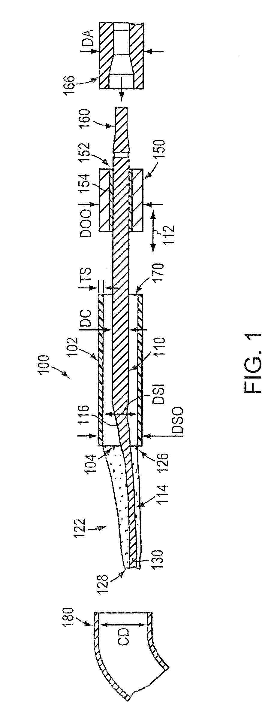
[0023]FIG. 1 shows an example (e.g., small diameter) thrombus retrieval device (or snare device) 100 according to an embodiment of this invention. Illustratively, the device 100 includes of a hollow, elongate, thin-walled polymer outer sheath 102. The sheath 102 may include a radiopaque marker located at or adjacent to the open distal end 104 for visualization under fluoroscopy. The polymer can be any one of a number of acceptable biocompatible polymers with sufficient structural strength to support a thin-walled (approximately 0.0020 inch maximum wall thickness TS) structure without rupture or other failure under normal use conditions. Alternatively or in addition, the thin-walled outer sheath 102 may be made from a metal tube, a metal spring coil with an outer polymer jacket, or a combination of a metal tube proximal portion and a thin-walled polymer tube distal portion (described below).

[0024]In one embodiment, the shea...


PUM

PropertyMeasurementUnit
thicknessaaaaaaaaaa
thicknessaaaaaaaaaa
thicknessaaaaaaaaaa

Abstract

This invention provides a device and controllably expansive tool tip for thrombus removal. According to one embodiment, the controllably expansive thrombus removal tool tip (e.g., a screen and / or mesh) may be collapsed by pushing on an actuating handle, and then advanced into a balloon or guiding catheter until a distal end of device has reached the thrombus. The tool tip is then expanded by pulling the actuating handle backward; and the radially extended (expanded) tool tip is moved to receive and substantially surround (e.g., encompass) the thrombus. The tool tip may then be collapsed again by pushing on the actuating handle to engage (tighten around) the thrombus, and the device may be withdrawn from a patient's body through the vascular system with the thrombus engaged by the tool tip.

Description

CROSS-REFERENCE TO RELATED APPLICATIONS[0001]The present application is related to commonly assigned copending U.S. patent application Ser. No. 12 / 098,201, which was filed on Apr. 4, 2008, by Richard M. DeMello, et al. for a SYSTEM AND METHOD FOR REMOVAL OF MATERIAL FROM A BLOOD VESSEL USING A SMALL DIAMETER CATHETER, which is a continuation-in-part of commonly assigned copending U.S. patent application Ser. No. 11 / 583,873, which was filed on Oct. 19, 2006, now published as U.S. Publication No. US2007-0118165 on May 24, 2007, by Jonathan R. DeMello, et al. for a SYSTEM AND METHOD FOR REMOVAL OF MATERIAL FROM A BLOOD VESSEL USING A SMALL DIAMETER CATHETER, which is a continuation-in-part of U.S. patent application Ser. No. 11 / 074,827, which was filed on Mar. 7, 2005, now published as U.S. Publication No. US2005-0234474 on Oct. 20, 2005, by Richard M. DeMello, et al. for a SMALL DIAMETER SNARE, which claims the benefit of U.S. Provisional Patent Application Ser. No. 60 / 551,313, which ...

Claims


Application Information

Patent Timeline
Patent Type & Authority Applications(United States)
IPC IPC(8): A61B17/221
CPCA61B17/221A61B2017/00367A61B2017/2215Y10T29/49826
Inventor DEMELLO, RICHARD M.DEMELLO, JONATHAN R.HEUSERFINLAYSON, MAUREEN A.
Owner VASCULAR SOLUTIONS
Why Eureka
Try Eureka