
Diagnostic device

a diagnostic device and a technology for diagnosing devices, applied in the direction of instruments, testing/monitoring control systems, nuclear elements, etc., can solve problems such as misdetection, conventional diagnostic devices suffer, and conventional diagnostic devices suffer

Active Publication Date: 2010-05-27
NEC CORP
View PDF3 Cites 16 Cited by
  • Summary
  • Abstract
  • Description
  • Claims
  • Application Information

AI Technical Summary

Benefits of technology

[0010]In a diagnostic device in which a set of attributes, whose degree of correlation with an attribute suffering a fault is higher than a predetermined criterion degree of correlation, is estimated to be the cause of the fault, as in Patent Document 2, the more complex the device or system being diagnosed, the larger is the number of candidates of the causes of the faults. Thus, it takes much time and labor until the true cause of the fault is identified. The reason may be such that, if the device being diagnosed is complicated, the number of parts that interrelate with one another is increased, with the result that the number of other attributes, strongly related with the attributes suffering from the fault, is appreciably increased.
[0013]It is another object of the present invention to provide a diagnostic device that may effectively locate the cause of faults by a narrowing-down (or focusing-up) technique based on the degree of change of attributes of data including a plurality of attributes as measured from the object being diagnosed.
[0014]It is yet another object of the present invention to provide a diagnostic device that is able to detect a fault and to estimate its cause by one and the same operational process.
[0045]If the change degree pattern has matched the pattern A1, it may be estimated that the fault occurred due to the cause a1. In similar manner, if the change degree pattern has matched the pattern A2, it may be estimated that the fault occurred due to the cause a2. It is thus possible to effectively find out the cause of the fault by a narrowing-down (or focusing-up) technique based on the change degree of each attribute of data including the multiple attributes as measured from the object being diagnosed.
[0049]Also, according to the present invention, it is possible to detect not only a fault that may be determined to be a fault only from the change degree of each attribute, but also a fault in which the change degree values of a plurality of attributes are involved in fault detection. It is because a fault may be detected based on a criterion change degree pattern generated based on past instances and a diagnostic object change degree pattern, with each pattern being a combination of values of the change degree of multiple attributes.
[0050]Moreover, according to the present invention, the cause of a fault that has occurred in an object being diagnosed may effectively be identified by a narrowing-down technique using past instances. It is because the cause of the fault may be estimated based on the criterion change degree pattern generated from past instances and the diagnostic object change degree pattern.

Problems solved by technology

The conventional diagnostic devices suffer from the following problems in connection with detection of faults:
Hence, if the values per se of an attribute at a given time point are not sufficient to give a decision on a fault, such that attribute values temporally before and after the given time point are also relevant in the fault, misdetection may be caused.
In addition, the conventional diagnostic device suffers from the following problem in connection with estimation of the causes of faults:
Thus, it takes much time and labor until the true cause of the fault is identified.
The conventional diagnostic device also suffers a problem that, since the processing steps for detection of a fault differ from those for estimation of the cause for the fault, it is not possible to use the same calculation module (program) for detection of the fault and for estimation of its cause.

Method used


Image

  • Diagnostic device
  • Diagnostic device
  • Diagnostic device

Examples


first exemplary embodiment

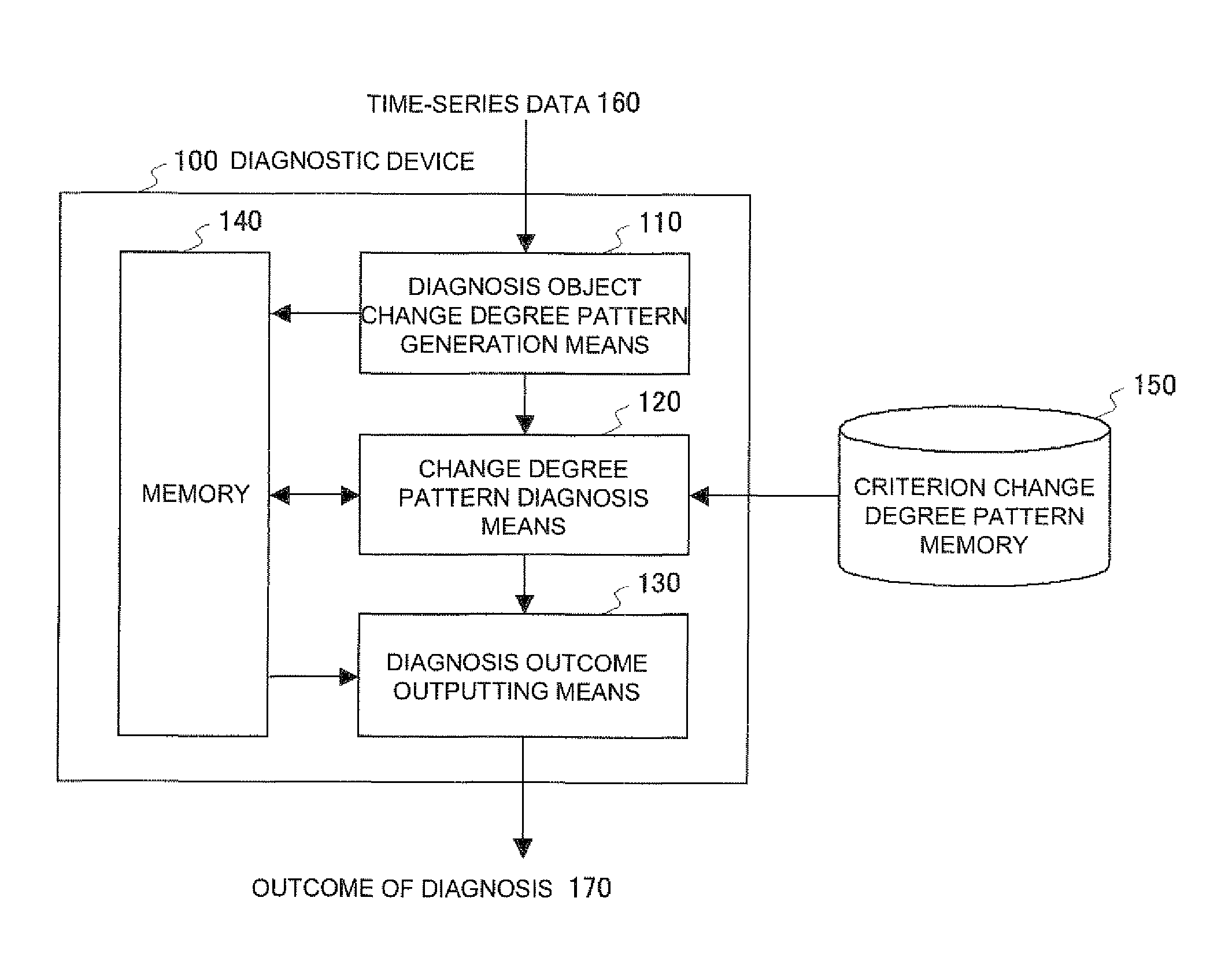
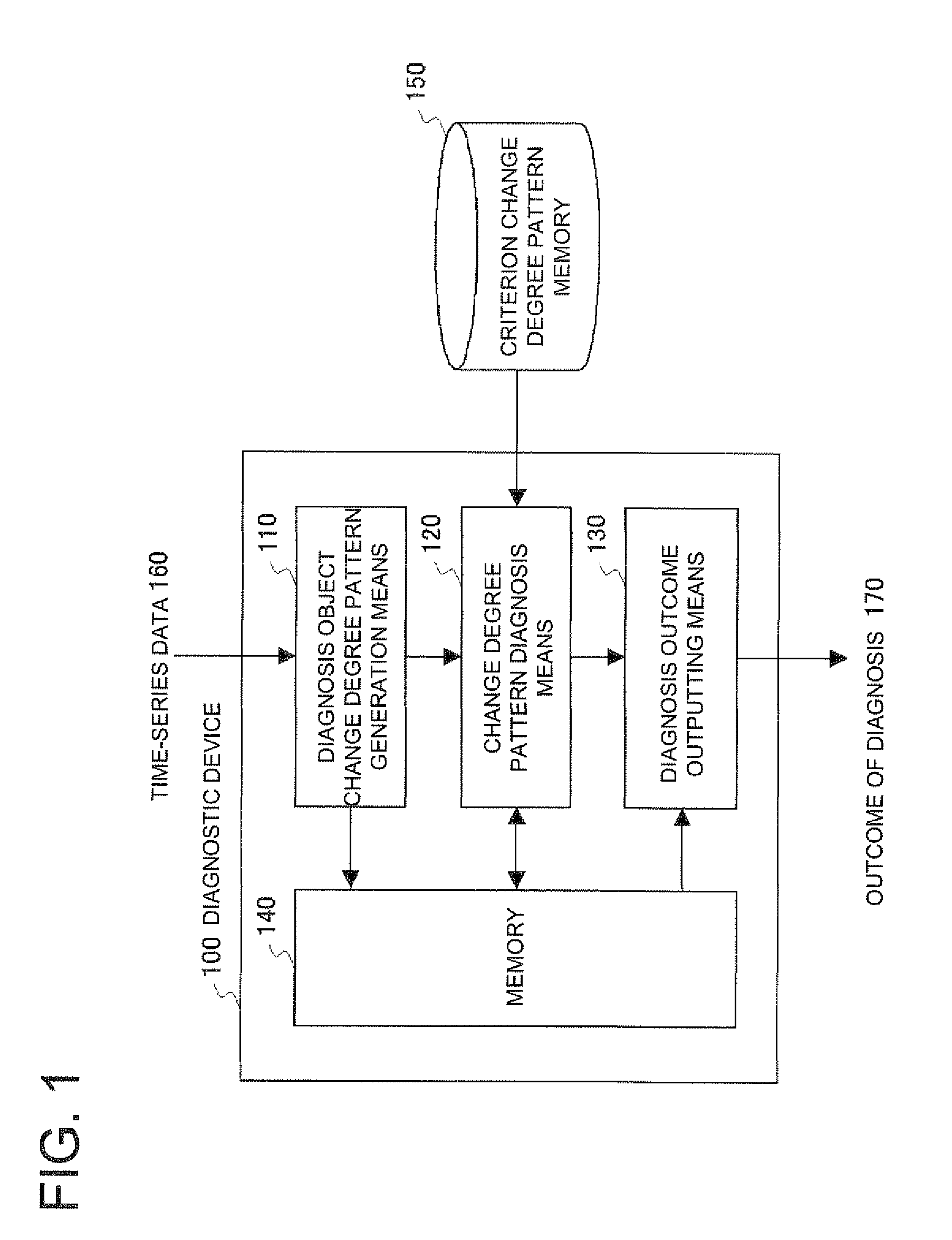
[0089]Referring to FIG. 1, a diagnostic device 100 according to a first exemplary embodiment of the present invention includes a diagnostic object change degree pattern generation unit 110, a change degree pattern diagnosis unit 120, a diagnosis outcome outputting unit 130 and a memory 140. A criterion change degree pattern memory 150 is connected to the diagnostic device 100. The diagnostic device 100 inputs a time-series data 160, including a plurality of attributes, as measured from an object being diagnosed, not shown. The diagnostic device compares a diagnostic object change degree pattern, generated from the time-series data 160, to a plurality of criterion change degree patterns, stored in the criterion change degree pattern memory 150, to detect the occurrence of a fault in the object being diagnosed. The diagnostic device also estimates the cause of the fault that has occurred to output an outcome of diagnosis 170.

[0090]With the number m of the attributes contained in the t...

second exemplary embodiment

[0120]Referring to FIG. 7, a diagnostic device 200 of a second exemplary embodiment of the present invention differs from the diagnostic device 100 of the first exemplary embodiment shown in FIG. 1 as to a change degree pattern diagnosis unit 210 provided in place of the change degree pattern diagnosis unit 120, and as to an attribute cardinality degree memory 220 connected to the device.

[0121]Referring to FIG. 8, the degree of cardinality of each attribute in the diagnosis of an event-to-be-diagnosed is stored in the attribute cardinality degree memory 220 in association with the event. In the example of FIG. 8, the degree of cardinality w11 of an attribute 1, the degree of cardinality w12 of an attribute 2, . . . , the degree of cardinality w1m of an attribute m are held in store. The degree of cardinality may be discrete values, such as a value 1 indicating cardinality or a value of 0, indicating non-cardinality, or a real number value specifying the degree of cardinality in more...

third exemplary embodiment

[0130]Referring to FIG. 9, there is shown a diagnostic device 300 according to a third exemplary embodiment of the present invention. This diagnostic device differs from the diagnostic device 200 of the second exemplary embodiment shown in FIG. 7 in including a change degree pattern diagnosis unit 310 in place of the change degree pattern diagnosis unit 210 and in including a layered criterion change degree pattern memory 320 in place of the criterion change degree pattern memory 150.

[0131]Data of a layered structure of a plurality of events as the subjects for diagnosis and a plurality of layer-based criterion change degree patterns are stored in the layered criterion change degree pattern memory 320. An example of such data is shown in FIG. 10. In this example, the data is in two layers, namely a first layer that detects a fault and a second layer that estimates the cause of the fault detected. The layered criterion change degree pattern memory holds in store one or more criterion...


PUM


Abstract

A diagnostic device which detects a fault and estimates its cause on the basis of the degree of variation of each attribute of data containing a plurality of attributes obtained by measuring a diagnosis subject. A diagnosis subject variation degree pattern generation means (110) calculates the degree of variation of each attribute of the diagnosis subject data containing the attributes obtained by measuring the diagnosis subject and generates a diagnosis subject variation degree pattern which is a combination of the degrees of variation of the attributes. A reference variation degree pattern storage device (150) stores a reference variation degree pattern composed of the degrees of variation of the attributes in association with the type of the fault and the diagnosis event of the type of the cause. A variation degree pattern diagnostic means (120) performs pattern matching of the diagnosis subject variation degree pattern and the reference variation degree pattern in the reference variation degree pattern storage device and diagnoses the diagnosis subject.

Description

REFERENCE TO RELATED APPLICATION[0001]The present application is claiming the priority of the earlier Japanese patent application No. 2007-074011 filed on Mar. 22, 2007, the entire disclosure thereof being incorporated herein by reference thereto.FIELD OF THE INVENTION[0002]This invention relates to a diagnostic device that detects a fault produced in an object being diagnosed and that estimates the cause of the fault based on data inclusive of a plurality of attributes as measured from the object being diagnosed.BACKGROUND OF THE INVENTION[0003]In the management of systems of various sorts, such as various devices, plant equipment or network systems, it is necessary to promptly detect the occurrences of faults and to inquire into the causes of the faults as necessary. For this reason, a large variety of diagnostic devices that detect the faults and estimate the causes thereof based on data as measured from various parts of devices or systems of various sorts as the objects for diag...

Claims


Application Information

Patent Timeline
IPC IPC(8): G06F11/00G06F11/30G06F17/00G01M99/00G06F15/00
CPCG05B23/0281G06N7/01
Inventor FUJIMAKI, RYOHEINAKATA, TAKAYUKISATOU, AKINORITSUKAHARA, HIDENORI
Owner NEC CORP
Learn More