Fluid machine and refrigeration cycle apparatus having the same

a technology of refrigeration cycle and flue, which is applied in the direction of lighting and heating apparatus, positive displacement liquid engine, liquid fuel engine, etc., to achieve the effect of suppressing heat transfer

Inactive Publication Date: 2010-06-03
PANASONIC CORP
View PDF5 Cites 13 Cited by
  • Summary
  • Abstract
  • Description
  • Claims
  • Application Information

AI Technical Summary

Benefits of technology

[0014]The present invention makes it possible to suppress heat transfer between the expansion mechanism and the compression mechanism in the fluid machine in which the expansion mechanism and the compression mechanism are accommodated in the same closed casing.

Problems solved by technology

In addition, the heat-insulating structure restricts the flow of the oil between the upper portion of the oil reservoir and the lower portion of the oil reservoir.

Method used


Image

  • Fluid machine and refrigeration cycle apparatus having the same
  • Fluid machine and refrigeration cycle apparatus having the same
  • Fluid machine and refrigeration cycle apparatus having the same

Examples


first embodiment

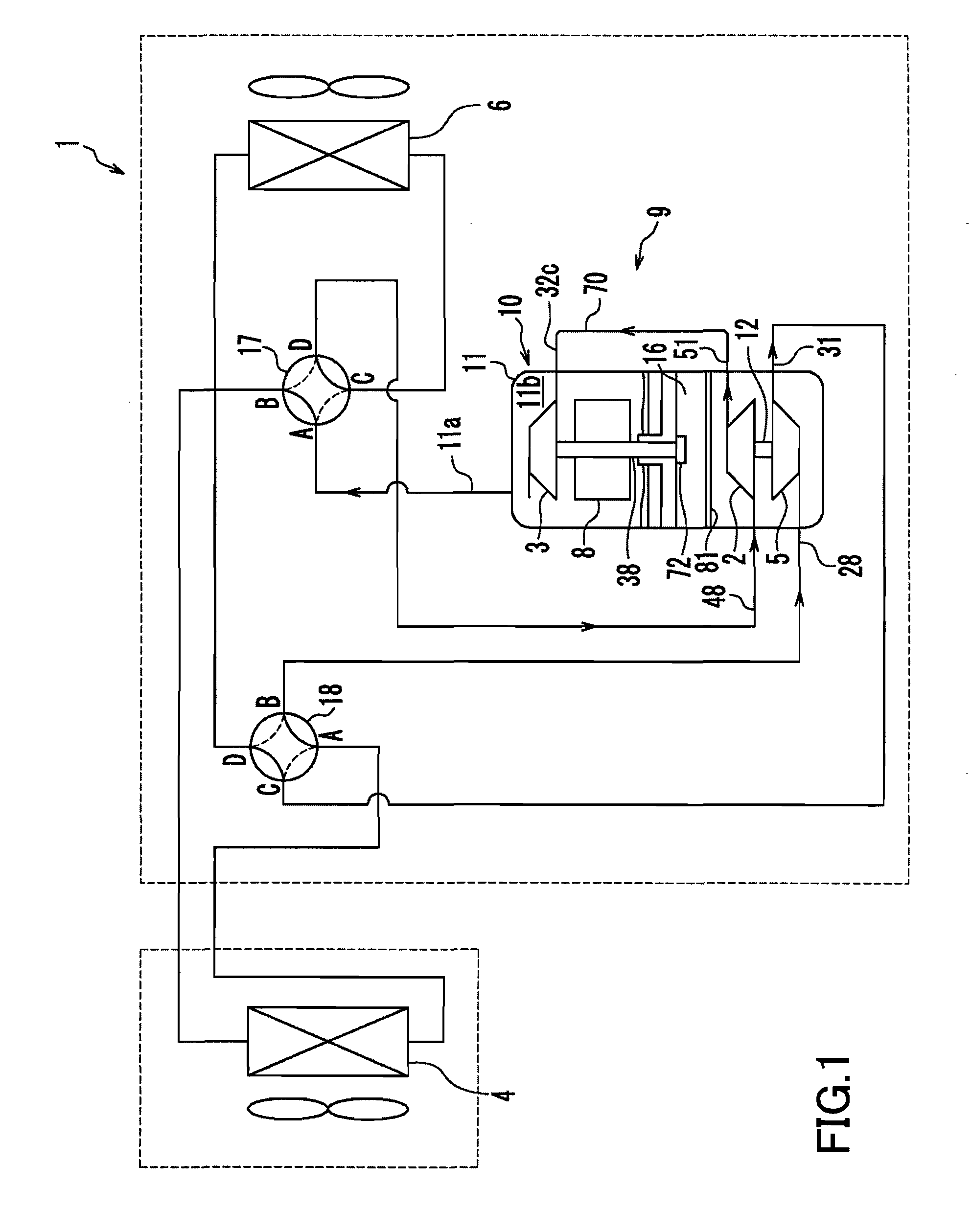
[0033]Hereinafter, embodiments of the present invention will be described with reference to a refrigeration cycle apparatus 1 shown in FIG. 1. It should be noted that the refrigeration cycle apparatus 1 is merely an example, and the present invention is not limited to the refrigeration cycle apparatus 1 described below.

[0034]1>

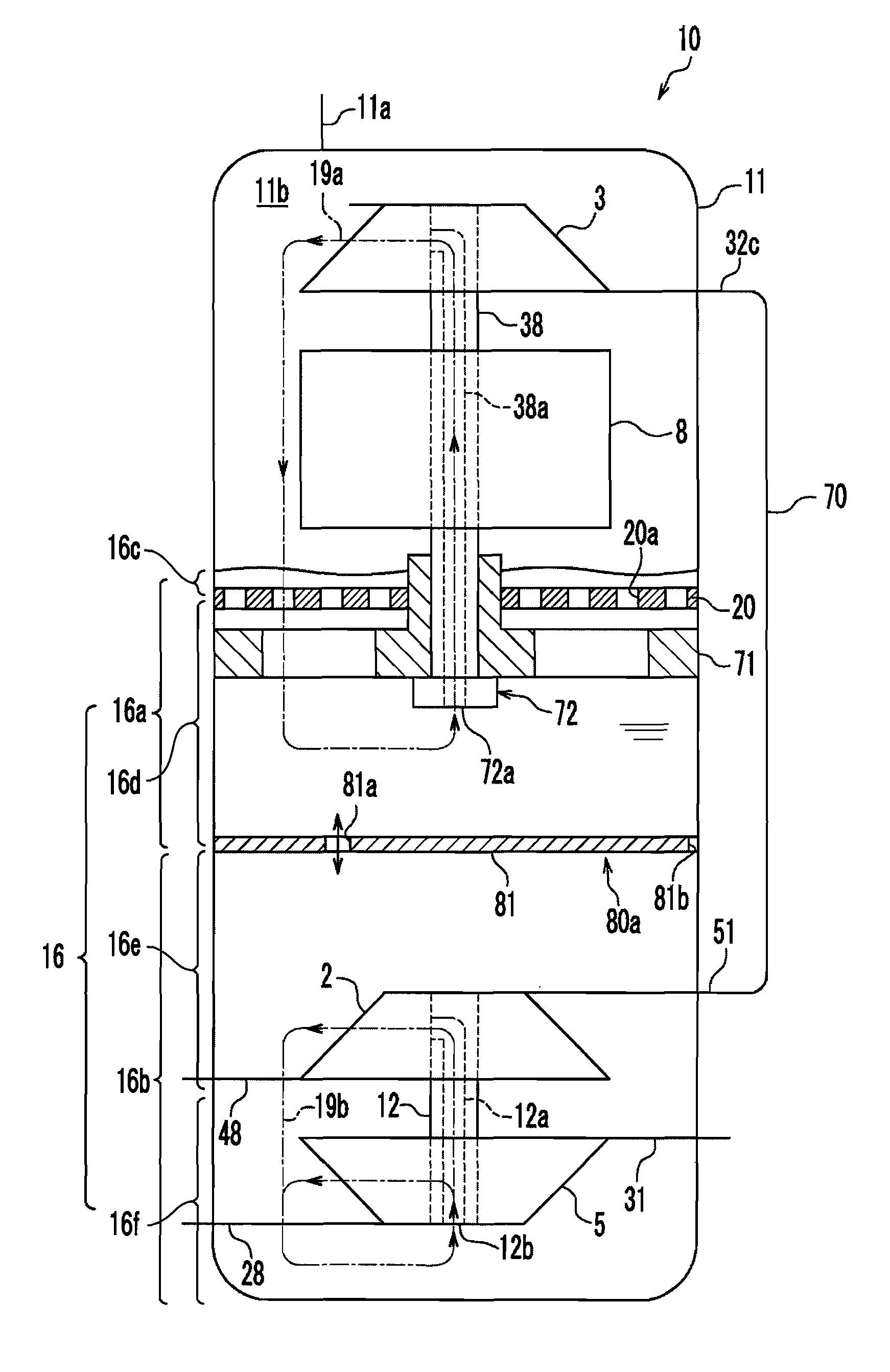
[0035]As shown in FIG. 1, the refrigeration cycle apparatus 1 includes a refrigerant circuit 9 provided with two four-way valves 17 and 18. The refrigerant circuit 9 includes a main compression mechanism 3, a first heat exchanger 4, a mechanical power recovery mechanism 5, a second heat exchanger 6, and a sub-compression mechanism 2. The refrigerant circuit 9 is filled with a refrigerant, as a working fluid, that is brought into a supercritical pressure state on the high pressure side of the refrigerant circuit 9. Specifically, the refrigerant circuit 9 is filled with carbon dioxide as a refrigerant.

[0036]It should be noted that in the present invention, the r...

second embodiment

[0101]FIG. 3 is a schematic configuration diagram of a fluid machine 10b according to a second embodiment. Hereinafter, the configuration of the fluid machine 10b according to the second embodiment will be described with reference to FIG. 3. The second embodiment will be described also with reference to FIG. 1, as in the first embodiment. Hereinbelow, components having substantially the same functions as those of the first embodiment are denoted by the same reference numerals, and a description thereof will be omitted.

[0102]As shown in FIG. 3, in the second embodiment, a heat-insulating structure 80b is provided in place of the heat-insulating structure 80a of the first embodiment. The heat-insulating structure 80b has a plate portion 82 and a tube portion 83. The plate portion 82 and the tube portion 83 may be integrated into one body. The plate portion 82 and the tube portion 83 may be separate bodies.

[0103]The plate portion 82 is disposed between the upper portion 16a and the low...

third embodiment

[0110]FIG. 4 is a schematic configuration diagram of a fluid machine 10c according to a third embodiment. Hereinafter, the configuration of the fluid machine 10c according to the third embodiment will be described with reference to FIG. 4. The third embodiment will be described also with reference to FIG. 1, as in the first embodiment. Hereinbelow, components having substantially the same functions as those of the first embodiment are denoted by the same reference numerals, and a description thereof will be omitted.

[0111]As shown in FIG. 4, in the third embodiment, a heat-insulating structure 80c is provided in place of the heat-insulating structure 80a of the first embodiment. The heat-insulating structure 80c has a plate member 84 and a tube member 86. The plate member 84 is disposed between the upper portion 16a and the lower portion 16b to partition the oil reservoir into the upper portion 16a and the lower portion 16b (separate the upper portion 16a and the lower portion 16b). ...


PUM


Abstract

A fluid machine (10) includes: a closed casing (11) having an oil reservoir (16) in its bottom portion; a main compression mechanism (3) supplied with oil contained in an upper portion (16a) of the oil reservoir; a rotation motor (8); a main compression mechanism side shaft (38) for coupling the main compression mechanism (3) and the rotation motor (8); a mechanical power recovery mechanism (5) disposed below the upper portion (16a) and recovering mechanical power from a working fluid; a sub-compression mechanism (2) disposed below the upper portion (16a); a mechanical power recovery shaft (16) for coupling the mechanical power recovery mechanism (5) and the sub-compression mechanism (2); and a heat-insulating structure (80) located between the upper portion (16a) and the mechanical power recovery mechanism (5) and restricting flow of oil between the upper portion (16a) of the oil reservoir (16) and a lower portion (16b) of the oil reservoir in which the mechanical power recovery mechanism (5) is provided.

Description

TECHNICAL FIELD[0001]The present invention relates to a fluid machine and a refrigeration cycle apparatus having the same.BACKGROUND ART[0002]As an example of a conventional fluid machine having an expansion mechanism and a compression mechanism, an expander-compressor unit is disclosed in JP 2005-299632 A. As shown in FIG. 18, an expander-compressor unit 130 described in JP 2005-299632 A includes a closed casing 120, a compression mechanism 121, a motor 122, and an expansion mechanism 123. The motor 122, the compression mechanism 121 and the expansion mechanism 123 are coupled to each other by a mechanical power recovery shaft 124. The expansion mechanism 123 recovers mechanical power from an expanding refrigerant. The mechanical power recovered by the expansion mechanism 123 is applied to the compression mechanism 121 via the mechanical power recovery shaft 124. Thereby, the power consumption of the motor 122 for driving the compression mechanism 121 is reduced. As a result, the c...

Claims


Application Information

Patent Timeline
Patent Type & Authority Applications(United States)
IPC IPC(8): F25B41/00F04C29/04
CPCF04C18/0215F04C18/10F04C18/3564F01C13/04F04C23/008F04C29/04F04C2240/809F04C23/005
Inventor TAKAHASHI, YASUFUMIHASEGAWA, HIROSHI
Owner PANASONIC CORP
Why Eureka
Try Eureka