Method for testing and calibrating a capacitive flex fuel sensor

a capacitive flex and fuel sensor technology, applied in the field of sensors, can solve the problems of increasing the complexity of the construction of such sensors, reducing the accuracy of the capacitive flex fuel sensor, and increasing the need for accurate flexible fuel sensors, so as to eliminate air gaps and achieve accurate calibration

Inactive Publication Date: 2010-06-03
DELPHI TECH INC
View PDF4 Cites 5 Cited by
  • Summary
  • Abstract
  • Description
  • Claims
  • Application Information

AI Technical Summary

Benefits of technology

[0011]In an alternate embodiment, the method further includes the step of compressing the test blank while it is in the fuel passage so as to substantially eliminate “air gaps” due to irregularities in either the inner surface of the fuel passage or the outer surface or geometry and / or size of the test blank. Minimizing or eliminating these “air gaps” allows for a more accurate calibration.

Problems solved by technology

On the other hand, fuel conductivity is very sensitive to water concentration.
Additionally, increasingly strict emissions-compliance requirements have only further strengthened the need for an accurate flexible fuel sensor.
This makes the construction of such sensors more complex and poses a potential for obstructing the fuel flow.
However, a drawback of such an approach is that using fuels in the manufacturing process (even for testing) complicates the handling and the cleaning of the sensor, as well as requires increased levels of care (e.g., safety measures) in the handling of the fuels.
Overall, this introduces extra expensive.
However, a drawback of this approach is that it will still require a special step to clean the sensor and / or related parts after the calibration and test phases.
The step of cleaning itself may involve or require the use of solvents, which can complicate the overall process as much as the use of fuel blends.
In sum, the use of oils or the like do not provide any appreciable improvement over use of fuels.

Method used


Image

  • Method for testing and calibrating a capacitive flex fuel sensor
  • Method for testing and calibrating a capacitive flex fuel sensor
  • Method for testing and calibrating a capacitive flex fuel sensor

Examples


Embodiment Construction

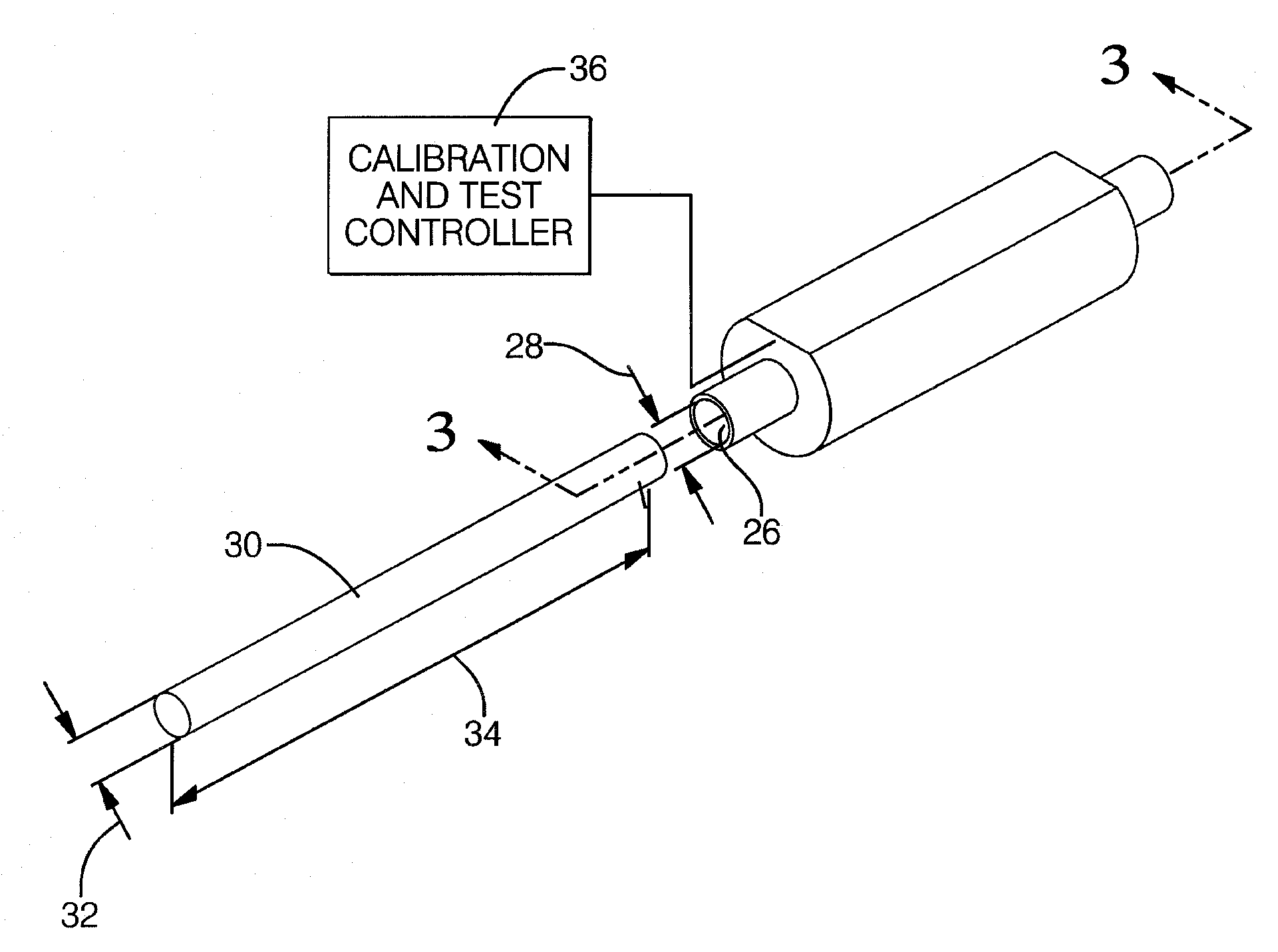
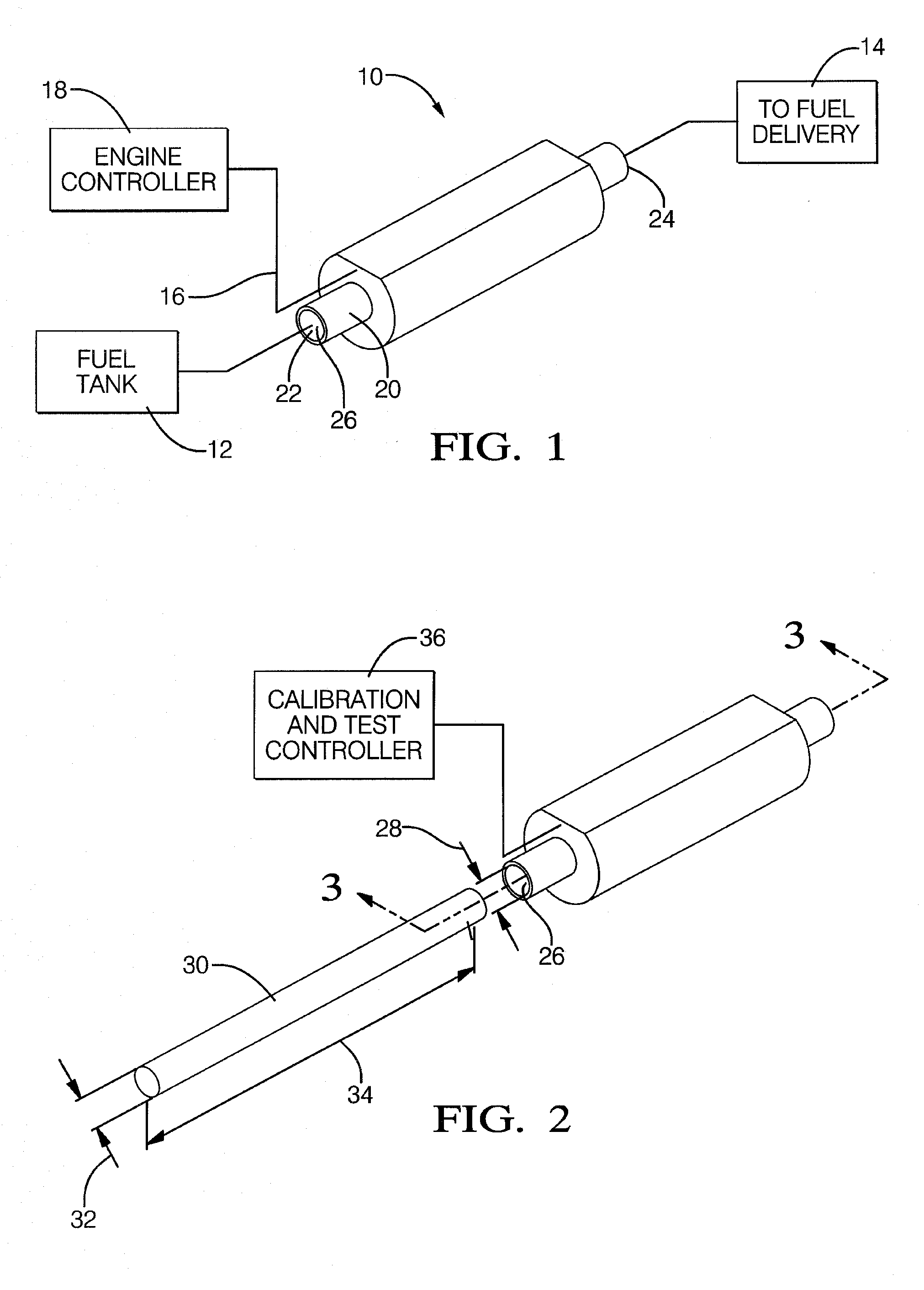
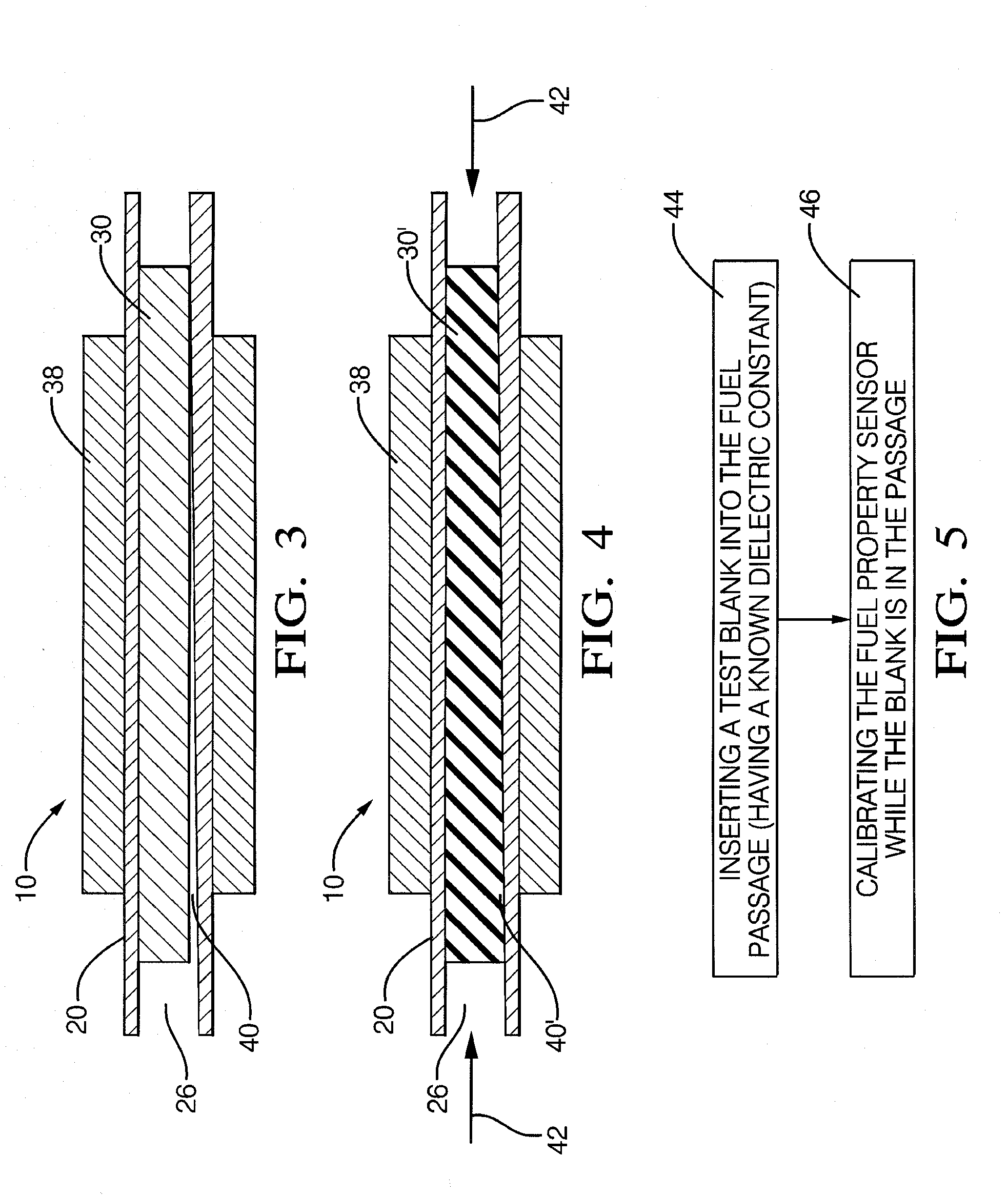
[0018]Referring now to the drawings wherein like reference numerals are used to identify identical components in the various views, FIG. 1 is a perspective view of a sensing apparatus 10 for sensing one or more properties of a fuel, such as a dielectric constant of a gasoline / ethanol blend. The sensing apparatus 10 (sometimes referred to herein as a “sensor”), as shown, is an in-line type fuel sensing apparatus that is coupled between a source of fuel, such as a fuel tank 12, and a destination, such as various fuel delivery apparatus 14 associated with an automotive vehicle internal combustion engine (not shown). The sensing apparatus 10, generally, includes a pair of sensing plates (not shown) surrounding an inner tube, in a concentric manner, which are connected to a closely-located electrical circuit with signal processing capability so as to generate an output signal 16. The sensing plates around the inner tube will form a capacitor. The material between the plates includes a fi...


PUM

PropertyMeasurementUnit
dielectric constantaaaaaaaaaa

Abstract

A method for calibrating a flex fuel sensing apparatus having a fuel passage involves the use of a generally solid test blank having a size and shape configured to match that of the fuel passage. The test blank comprises material having a known, predetermined dielectric constant. The test blank is inserted into the fuel passage where the dielectric constant of the test blank is operative to simulate the presence of various gasoline and ethanol fuel blends. The test blank may also comprise a deformable/compressible solid such as rubber where the test blank is compressed during calibration to eliminate air gaps or the like, improving accuracy. The use of the solid test blank reduces complexity compared to using actual gasoline/ethanol blends for calibration as well as reduces post-calibration cleanup.

Description

CROSS-REFERENCE TO RELATED APPLICATIONS [0001]This application is related to co-pending U.S. application Ser. No. ______ filed ______, 2008 entitled “FUEL SENSOR (Docket No. DP-317807), now pending, owned by the common assignee of the present invention, the disclosure of which is hereby incorporated by reference herein in its entirety.TECHNICAL FIELD [0002]The present invention relates generally to sensors, more particularly to a fuel sensor having sensing plates that do not obstruct a fuel passage, and still more particularly to a method for testing and calibrating such sensors.BACKGROUND OF THE INVENTION [0003]Due to the fact that ethanol is a renewable fuel, and for other reasons as well, the use of ethanol and ethanol blends (i.e., ethanol and gasoline) continues to grow. For example, flexible fuel vehicles are known that are designed to run on gasoline as a fuel or a blend of up to 85% ethanol (E85). Properties of such fuels, such as its conductivity or dielectric constant, can...

Claims


Application Information

Patent Timeline
Patent Type & Authority Applications(United States)
IPC IPC(8): G01N33/22
CPCG01N33/2852
Inventor HERNANDEZ, NORBERTOURQUIDI, CARLOS A.AGUINAGA, ESAU
Owner DELPHI TECH INC
Why Eureka
Try Eureka