Applicator for applying fluid to a substrate, comprising valve mechanisms, method for cleaning said applicator, and valve mechanisms for said applicator

a technology for applying fluids and substrates, which is applied in the direction of cleaning processes, cleaning apparatus, cleaning using liquids, etc., can solve the problems of affecting the cleaning effect, etc., and achieves the effects of reducing the risk of damage, avoiding clogging, and being sensitive to damag

Inactive Publication Date: 2010-06-03
J ZIMMER MASCHENBAU GES
View PDF5 Cites 23 Cited by
  • Summary
  • Abstract
  • Description
  • Claims
  • Application Information

AI Technical Summary

Benefits of technology

[0018]A further advantage of the above embodiment lies in that, after the distributing fluid chamber has been cleaned according to the invention, the fluid duct between the distributing fluid chamber and the associated application nozzle can also be cleaned by the fact that the detachably mounted valve housing is removed in case of major contamination. The valve housing and the valve piston are easily removed and remounted on the nozzle side of the application device, that is, on the lower side of the device which forms the application side. Such partial dismounting may be necessary if a change of fluid is to be made, e.g. a change of colour. Unlike conventional application devices, the adjusting pistons, i.e. adjusting devices arranged for this purpose on the upper or rear side of the application device, are not dismounted. This is a considerable advantage, as it is the adjusting devices that are very sensitive to damage. The slightest damage can already falsify adjustments within a range of a few micrometres. Flushing of the distributing fluid chamber with the cleaning valve device according to the invention also covers the adjusting pistons for cleaning, without dismounting taking place on the upper/rear side of the application device.
[0019]The valve device of an application device according to the invention even in the single form achieves the result that, along the straight valve duct path between the su

Problems solved by technology

Contamination occurs in particular after an initial assembly.
But breakdowns due to deposits also occur while operation is ongoing.
Conventional application devices then usually have

Method used


Image

  • Applicator for applying fluid to a substrate, comprising valve mechanisms, method for cleaning said applicator, and valve mechanisms for said applicator
  • Applicator for applying fluid to a substrate, comprising valve mechanisms, method for cleaning said applicator, and valve mechanisms for said applicator
  • Applicator for applying fluid to a substrate, comprising valve mechanisms, method for cleaning said applicator, and valve mechanisms for said applicator

Examples


Embodiment Construction

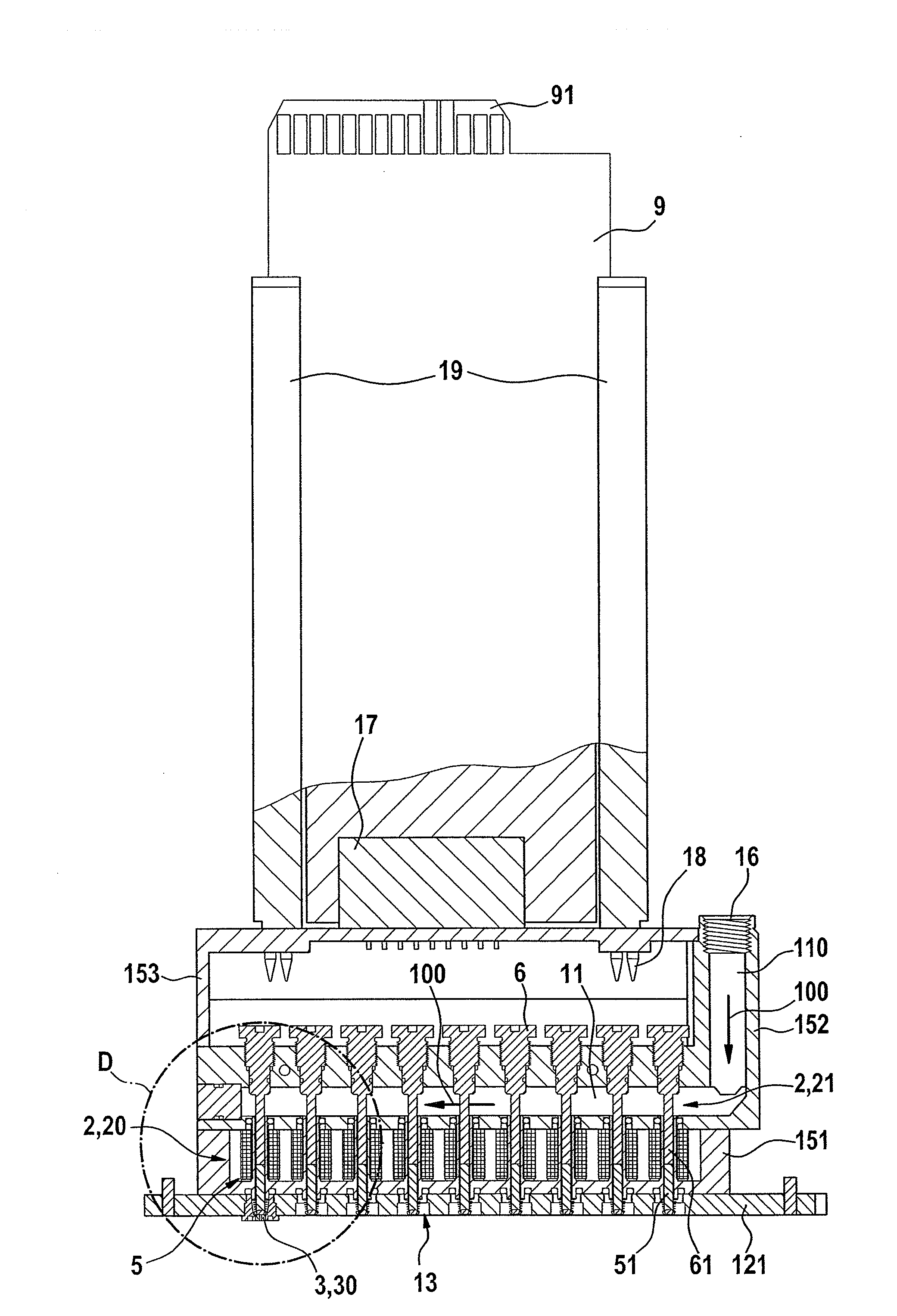
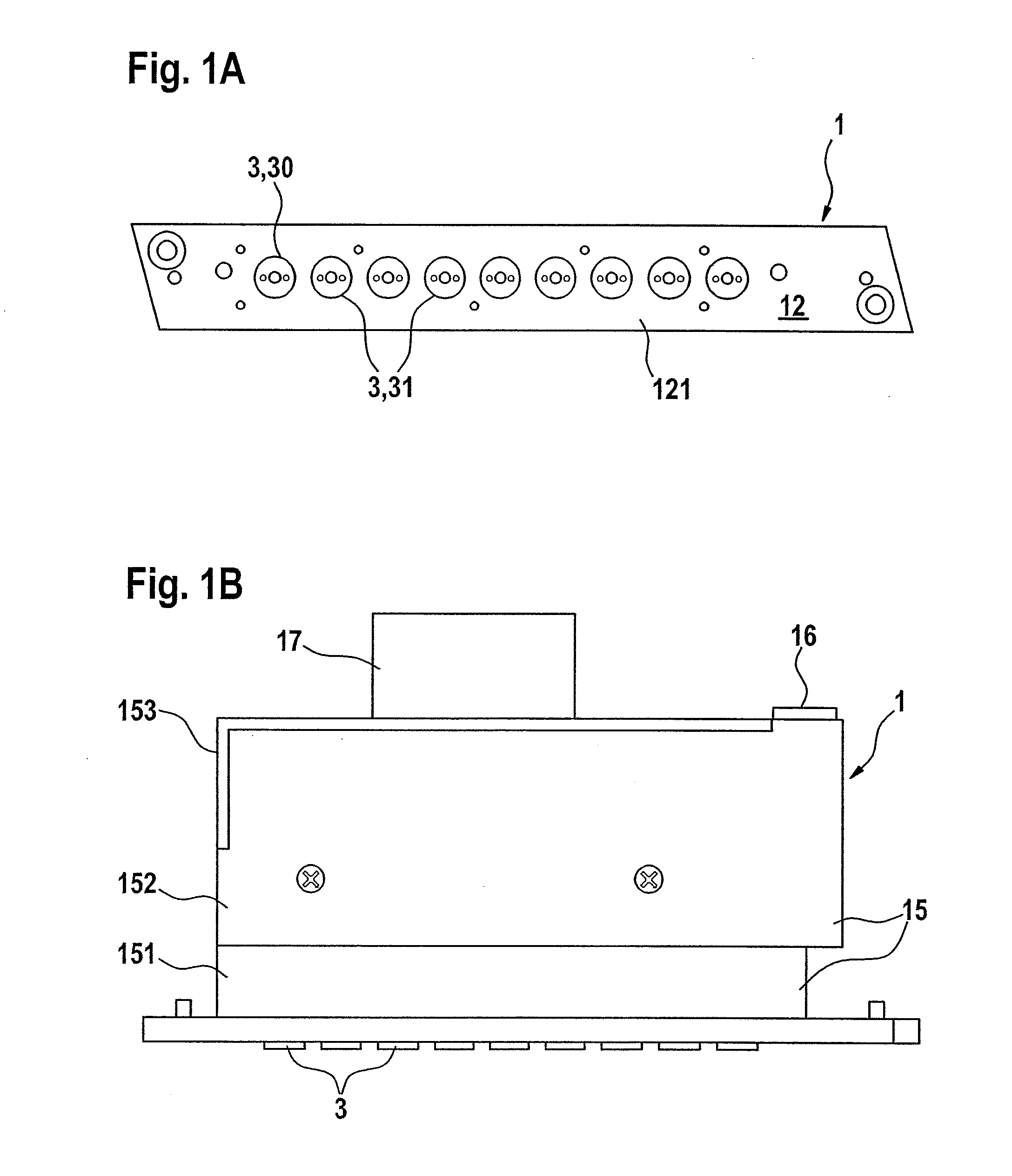
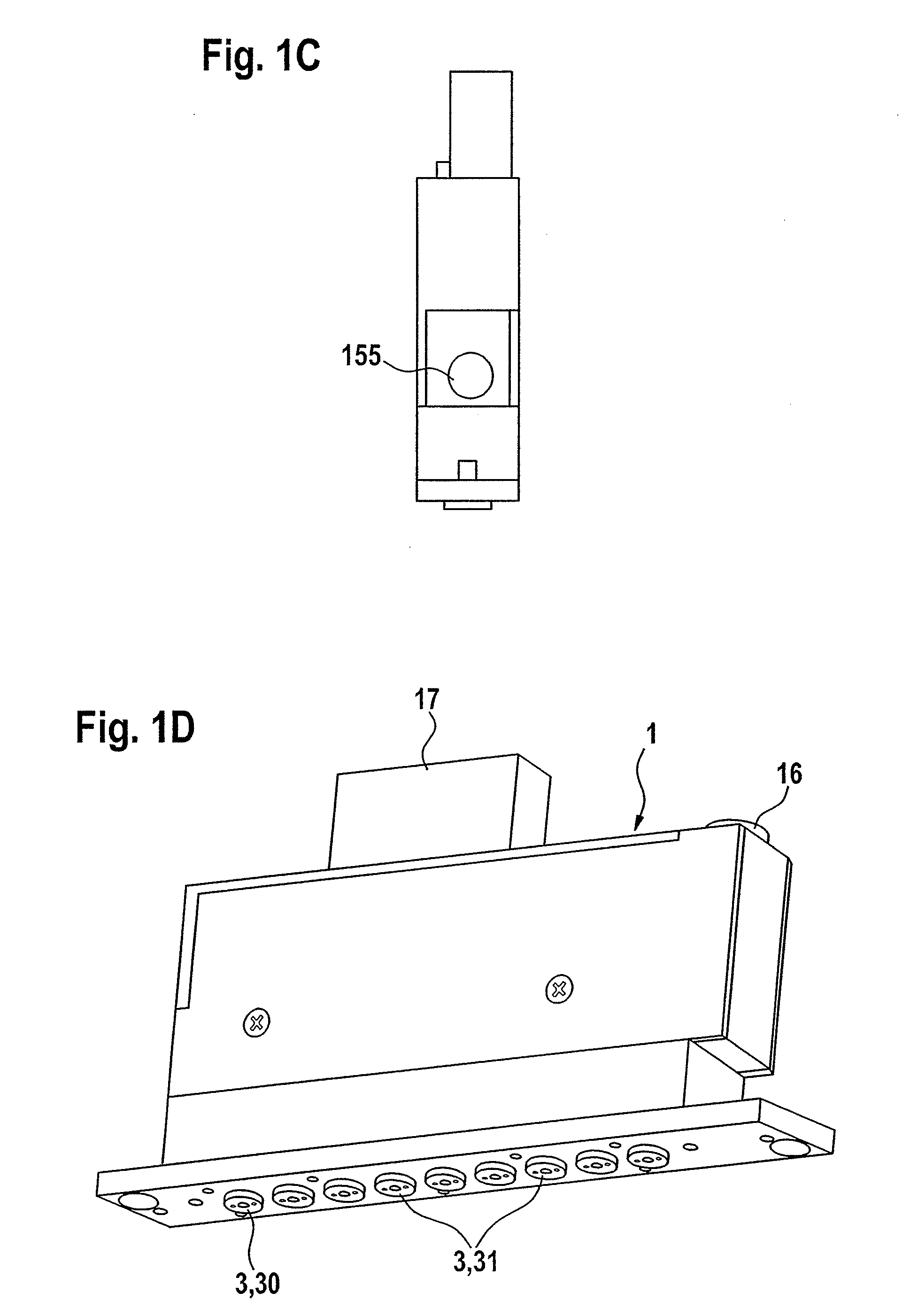
[0026]The application device according to the invention shown in FIGS. 1A to D comprises a box-like valve body 15 which is composed of a lower socket portion 151 and an upper cover portion 152. The lower portion 151 is closed by a narrow elongate nozzle plate 121 which receives valve nozzles 3. The valve nozzles 3 are arranged in a straight row on the nozzle / application side 12. On the opposite side, the application device 1 has an electrical plug-in connection 17 and a connecting opening 16 for application fluid. In the practical example the row of valve nozzles 3 is defined by eight application valve nozzles 31 and one cleaning valve nozzle 30 which closes the row of nozzles. The cleaning valve nozzle 30 is according to the invention arranged at the end of the row of nozzles opposite the connecting opening 16.

[0027]As can be seen from the sectional view in FIG. 2, the valve body 15 is connected to an electronic power switching device 9. This switching device 9 is connected by mean...


PUM


Abstract

Disclosed is an applicator (1) for applying fluid to a substrate, comprising valve mechanisms (21) which are arranged in a row and are each equipped with an application valve nozzle (31), and a distributing fluid chamber (11) that has a fluid intake duct (110). A cleaning valve mechanism (21) which is incorporated into the row of application valve mechanisms (21) and is fitted with a cleaning valve nozzle (30) is associated with the fluid intake duct (110). A flow path (100) for cleaning the fluid chamber (11) is formed between the fluid intake duct (110) and the cleaning valve mechanism (20) in the distributing fluid chamber (11), said flow path (100) being effective when the cleaning valve nozzle (30) is open. Also disclosed is a method for cleaning said applicator (1). In said method, pressurized cleaning fluid is applied to the distributing fluid chamber (11), the application valve mechanisms (21) are kept closed while the cleaning valve nozzle (30) is opened, and the cleaning valve nozzle (30) is then closed while the application valve mechanisms are opened when the pressurized cleaning fluid is applied to the distributing fluid chamber (11). A valve mechanism (2) of the applicator (1) encompasses a detachably mounted nozzle diaphragm (3, 4) which unblocks a valve piston (51) in the removed state. The valve mechanism (2) further encompasses a straight fluid duct that remains free of flow corners. A setting piston (61) is movably mounted for adjusting and setting the stroke of the valve piston (51).

Description

[0001]This application is a 35 U.S.C. §371 filing of International Patent Application No. PCT / EP2008 / 004122 filed May 20, 2008, which designates the United States and claims the benefit of European Application No. 07090124.4 filed Jun. 14, 2007.BACKGROUND OF THE INVENTION[0002]The invention concerns an application device for applying fluid to a substrate, comprising valve devices which are arranged in a row and are each equipped with an application valve nozzle for emitting the fluid under pressure and with associated valve actuating device for controlling the emission of fluid by closing and opening the application valve nozzles, and comprising a common distributing fluid chamber which can be subjected to pressure from the fluid and which connects the application valve devices to each other for admission of the fluid, the distributing fluid chamber being provided with a fluid intake duct which is arranged in such a way that the fluid which is under pressure in the distributing flui...

Claims


Application Information

Patent Timeline
IPC IPC(8): B05C5/02B08B3/00B05B15/55
CPCB05B1/20B05B1/3053B05C5/0279B05C5/0225B05B15/025B05B15/55
Inventor ACHRAINER, JOHANN
Owner J ZIMMER MASCHENBAU GES
Why Eureka
Try Eureka