
Cell isolation on photovoltaic modules for hot spot reduction

a photovoltaic module and cell isolation technology, applied in photovoltaics, electrical equipment, semiconductor devices, etc., can solve problems such as reverse bias degradation, undesired “hot spot” effect, and solar array degradation

Inactive Publication Date: 2010-06-03
APPLIED MATERIALS INC
View PDF11 Cites 21 Cited by
  • Summary
  • Abstract
  • Description
  • Claims
  • Application Information

AI Technical Summary

Benefits of technology

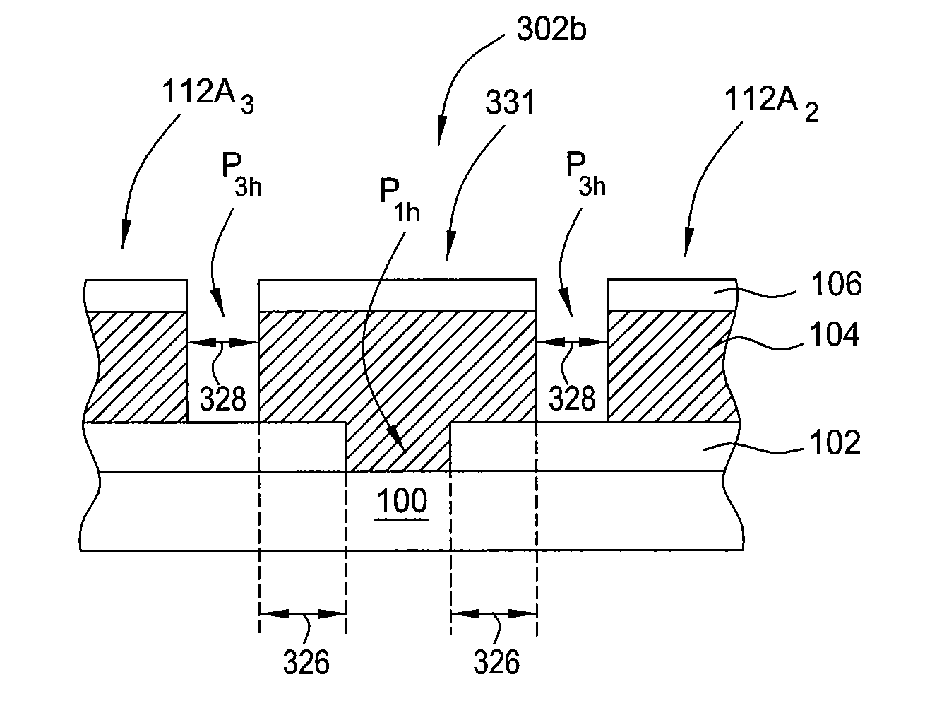
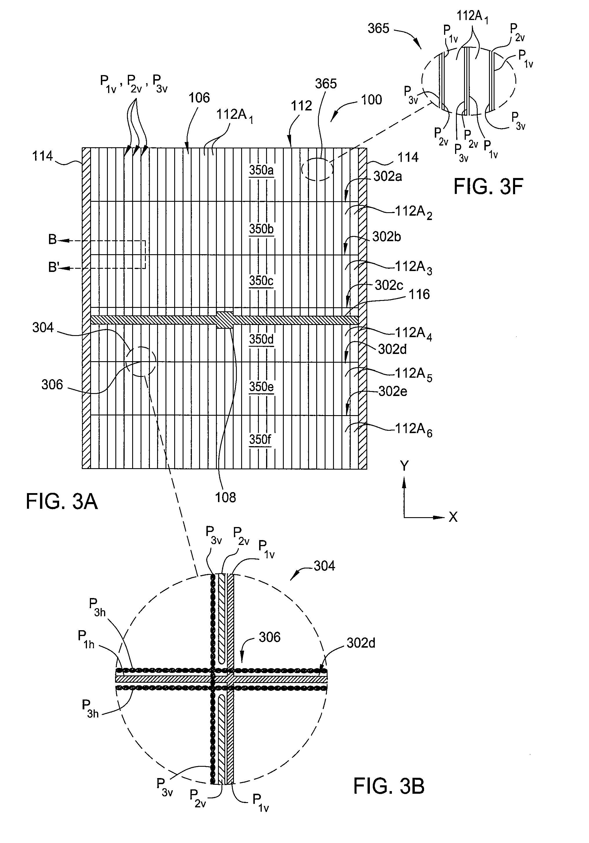
[0011]In yet another embodiment, a method for fabricating a series of solar cell arrays on a substrate includes forming a transparent conductive oxide layer on a surface of a substrate, forming a plurality of first vertical scribing lines in the transparent conductive oxide layer to form a patterned transparent conductive oxide layer, forming a film stack over the patterned transparent conductive oxide layer, forming a plurality of second vertical scribing lines in the film stack to form a patterned film stack, forming a back metal layer over the patterned film stack, forming a plurality of third vertical scribing lines in the back metal layer to form a patterned back metal layer, and forming a plurality of first horizontal scribing lines by removing a portion of the back metal layer and a portion of the film stack, wherein the first horizontal scribing lines are substantially perpendicular to the vertical scribing lines and are placed in a spaced apart relationship to each other to form at least two or more segments to proportionally reduce the current passing through each segment.

Problems solved by technology

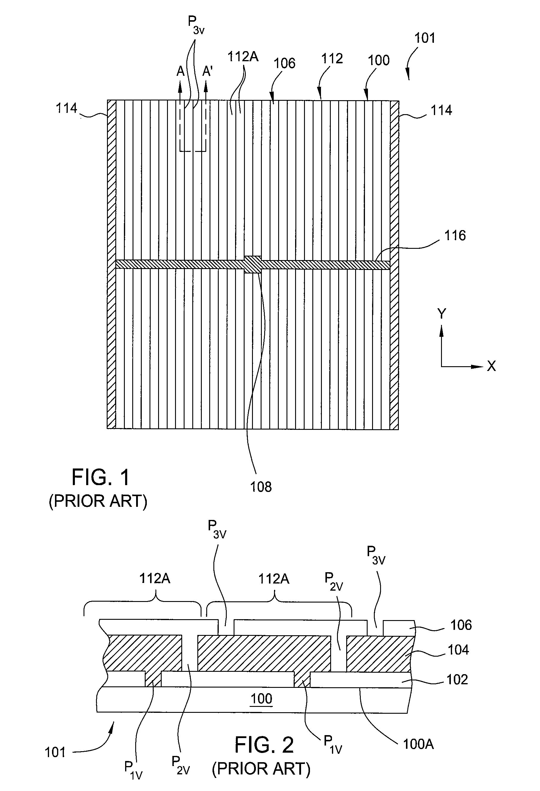
However, a problem arises when individual solar cells 112A or portions of the individual solar cells 112A are not generating electricity, such as when some subset of solar cells are shaded.
In an extreme case, the formed “hot-spot” may destroy a photovoltaic cell and generate cracks in the substrate 100, and thus degrade the solar array, thereby resulting in scraping of the PV module 101 containing the solar array 112.
Similarly, uneven current distribution may also result in current accumulation at certain spot of the solar cell arrays, thereby resulting in an undesired “hot-spot” effect or reverse-bias degradation.

Method used


Image

  • Cell isolation on photovoltaic modules for hot spot reduction
  • Cell isolation on photovoltaic modules for hot spot reduction
  • Cell isolation on photovoltaic modules for hot spot reduction

Examples


Embodiment Construction

[0031]Embodiments of the present invention provide methods for fabricating a series of solar cell arrays on a substrate to prevent the hot spot effect from damaging the formed solar cell device. In one embodiment, the series of solar cells formed on a substrate are scribed in a predetermined pattern so as to substantially eliminate current accumulation or overheating at various locations along the array of solar cells. In one example, current accumulation or overheating of regions within the solar cell arrays may be substantially eliminated by forming solar cells in a desired pattern that is configured to reduce the maximum possible current flowing through each solar cell in the formed solar cell array, therefore, reducing the maximum possible current flowing across any shaded portion of a formed solar cell array and preventing damage to the formed device.

[0032]FIG. 3A depicts a plain view of a plurality of solar cell arrays formed on the substrate 100 having a desired scribing patt...


PUM


Abstract

Embodiments of the present invention provide methods for fabricating a solar cell on a substrate that have proportionally reduced current to minimize or reduce the likelihood of shading of a portion of the solar cell causing damage to the formed device. In one embodiment, a method for fabricating a series of solar cell arrays on a substrate includes providing a substrate having a TCO layer formed thereon, forming a first plurality of vertical scribing lines and a first plurality of horizontal scribing lines in the TCO layer, forming a film stack and a back metal layer on the scribed TCO layer, and forming a second plurality of the horizontal scribing lines in the film stack and the back metal layer, wherein the second plurality of horizontal scribing lines comprise pairs of scribing lines formed adjacent to each respective one of the first plurality of the horizontal scribing lines formed in the TCO layer.

Description

BACKGROUND[0001]1. Field of the Invention[0002]The present invention relates to methods for forming solar cell arrays on photovoltaic modules on a substrate, more particularly, for forming solar cell arrays on photovoltaic modules on a substrate with minimum hot spot effect.[0003]2. Description of the Background Art[0004]Photovoltaic (PV) arrays or solar arrays are devices which convert sunlight into direct current (DC) electrical power. Photovoltaic (PV) arrays or solar arrays are typically comprised by a plurality of photovoltaic cells, also known as solar cells. PV or solar cells typically have one or more p-i-n junctions. Each junction comprises two different regions within a semiconductor material where one side is denoted as the p-type region and the other as the n-type region. When the p-i-n junction of the PV cell is exposed to sunlight (consisting of energy from photons), the sunlight is directly converted to electricity through a PV effect. Each of the PV solar cells gener...

Claims


Application Information

Patent Timeline
IPC IPC(8): H01L31/042H01L21/304
CPCH01L31/042H01L31/046Y02E10/50H01L31/18H01L31/0201H01L31/0463
Inventor JIA, RENHEWANG, DAPENGFREI, MICHELTANNER, DAVIDEBERSPACHER, CHRIS
Owner APPLIED MATERIALS INC
Learn More