Method and apparatus for controlling fluctuations in multiphase flow production lines

a multi-phase flow and production line technology, applied in fluid dynamics, water supply installation, borehole/well accessories, etc., can solve the problems of difficult to achieve steady state conditions in a slugging flow line system, non-optimal lifting operations, and considerable problems

Inactive Publication Date: 2010-06-03
SCHLUMBERGER TECH CORP
View PDF10 Cites 14 Cited by
  • Summary
  • Abstract
  • Description
  • Claims
  • Application Information

AI Technical Summary

Benefits of technology

[0014]In another preferred variant of the invention, the control unit is operational without measurements performed at a slug catcher or separator unit. The term “operational” is defined herein as meaning being capable of performing the desired operation. The invention can thus be applied advantageously in subsea production facilities. The measuring device and the flow booster and choke can all be located subsea, preferably between the well and marine riser structure to prevent slugging going through the riser, thereby preventing for example a negative impact on gas lifting.

Problems solved by technology

Slugging is by definition a transient phenomenon, and steady state conditions are hard to achieve in a slugging flow line system.
The instabilities caused by slug flow give rise to considerable problems in the well production facilities and operations of downstream processing plants.
These problems include poor separation of water, oil and gas, overflow at the separator stages of the flow line, large and varied load on compressors and pumps, pressure variations in pipelines and marine risers resulting for example in non-optimal lifting operations.
As described in the U.S. Pat. No. 7,434,621 to Aarvik and Uv and U.S. Pat. No. 7,239,967 to Havre, the method of choking the flow line to such extent that the operation point is outside the unstable flow regime has the severe disadvantage of decreasing the output flow to a level substantially lower than the capacity of the flow line.
If the estimated volume of the incoming slugs exceeds the liquid slug handling capacity of the separator, a throttling valve located upstream of the separator is choked.

Method used


Image

  • Method and apparatus for controlling fluctuations in multiphase flow production lines
  • Method and apparatus for controlling fluctuations in multiphase flow production lines
  • Method and apparatus for controlling fluctuations in multiphase flow production lines

Examples


Embodiment Construction

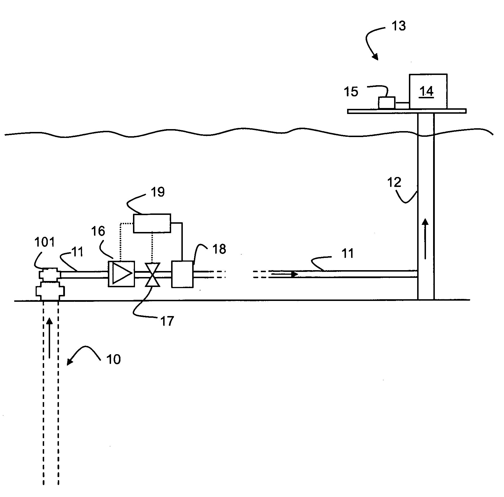
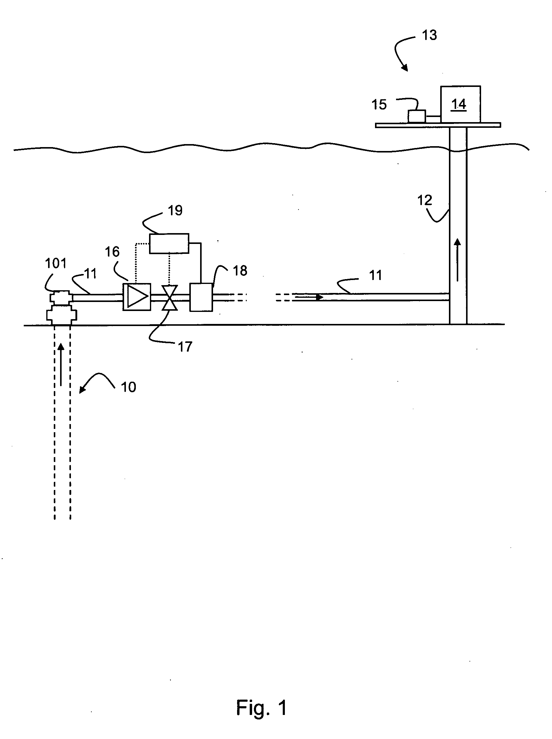
[0026]A typical subsea system is made up of a number of key components schematically illustrated in FIG. 1. Those components include a number of production and injection wells 10. These wells are then attached through flow lines 11 from the well head 101 to a riser 12 in which fluids are transported to the topsides production system 13. Typically as part of the surface installation 13 there are slug catcher or separator units 14 together with control and monitoring systems 15.

[0027]The reservoir fluid flowing in these flow lines could be gas, oil and / or water depending upon the characteristics of the reservoir, original fluid in the reservoir, design parameters of the flow lines / riser etc and some key flow parameters. The occurrence of slugging or slug flow in the installation is thought to be dependent on many design and flow parameters. There is hence currently no full analytical description of the process known.

[0028]In this example of the invention it is therefore proposed to fi...


PUM


Abstract

Methods and apparatus for controlling the effects of slug flow in a flow line installation from a subterranean well to a production facility are described using in the flow line a flow conditioning unit, such as a flow booster and a flow choke, and a measuring device for measuring one or more parameter determined to be the most significant installation design or flow parameters correlated with the slug volume, connected to a control unit receiving input from the measuring device and using a relationship between slug volume and the one or more most significant parameters to control the flow conditioning unit.

Description

FIELD OF THE INVENTION[0001]This invention is generally related to predicting, stabilizing or controlling slugging in multiphase flow, in particular in long flow lines (tiebacks) between subsea well heads and production facilities at the sea surface.BACKGROUND[0002]Multiphase transport in long flow lines or pipelines from subterranean, particularly subsea wells to common production installations such as production systems, separators, risers, whether located subsea or at the surface or offshore or onshore, often shows a propensity to develop fluctuations, commonly referred to as slugs.[0003]Slugs are assumed to be caused be gravity effects or hydrodynamical effects based on differences between the liquid and gaseous phases of the flow. Such effects lead typically to a localized accumulation of the liquid phase, i.e. a slug. In particular, liquid slugs are usually formed from flowing gaseous environment as a result of temperature and pressure decrease during the flow in production tu...

Claims


Application Information

Patent Timeline
Patent Type & Authority Applications(United States)
IPC IPC(8): F15D1/02
CPCE21B43/12E21B43/01Y10T137/0324Y10T137/8376Y02P80/10
Inventor JAMALUDDIN, ABUL K. M.KHAN, IFADAT ALICARNEGIE, ANDREW JOHN
Owner SCHLUMBERGER TECH CORP
Why Eureka
Try Eureka