
Plasma etching apparatus

a technology of etching apparatus and plasma, which is applied in the direction of electrical equipment, decorative arts, electric discharge tubes, etc., can solve the problems of difficult control of etching characteristics, difficult to realize uniform etching, and portion of the substrate, so as to achieve the effect of improving etching characteristics

Inactive Publication Date: 2010-06-03
TOKYO ELECTRON LTD
View PDF12 Cites 17 Cited by
  • Summary
  • Abstract
  • Description
  • Claims
  • Application Information

AI Technical Summary

Benefits of technology

The present invention provides a plasma etching apparatus that can improve the controllability of etching characteristics by way of precisely and freely controlling the flow or density distribution of a processing gas in the plasma generation region. This is achieved by introducing different etchant gas species from two directions, namely, from the upper and side portions of the processing chamber, and controlling the gas introduction rates through mass flow control units. The apparatus also includes a central gas inlet and a side gas inlet for introducing the etchant gas and dilution gas, respectively, which allows for a precise and free control of the gas flow and density distribution in the plasma generation region. The apparatus can be used for various etching processes and is particularly useful for improving the controllability of etching characteristics on a substrate.

Problems solved by technology

However, in the conventional parallel plate plasma etching apparatus, it is difficult to realize uniform etching characteristics on a substrate to be processed and, further, it is hard to control etching characteristics, especially on a peripheral portion of the substrate.

Method used


Image

  • Plasma etching apparatus
  • Plasma etching apparatus
  • Plasma etching apparatus

Examples


first embodiment

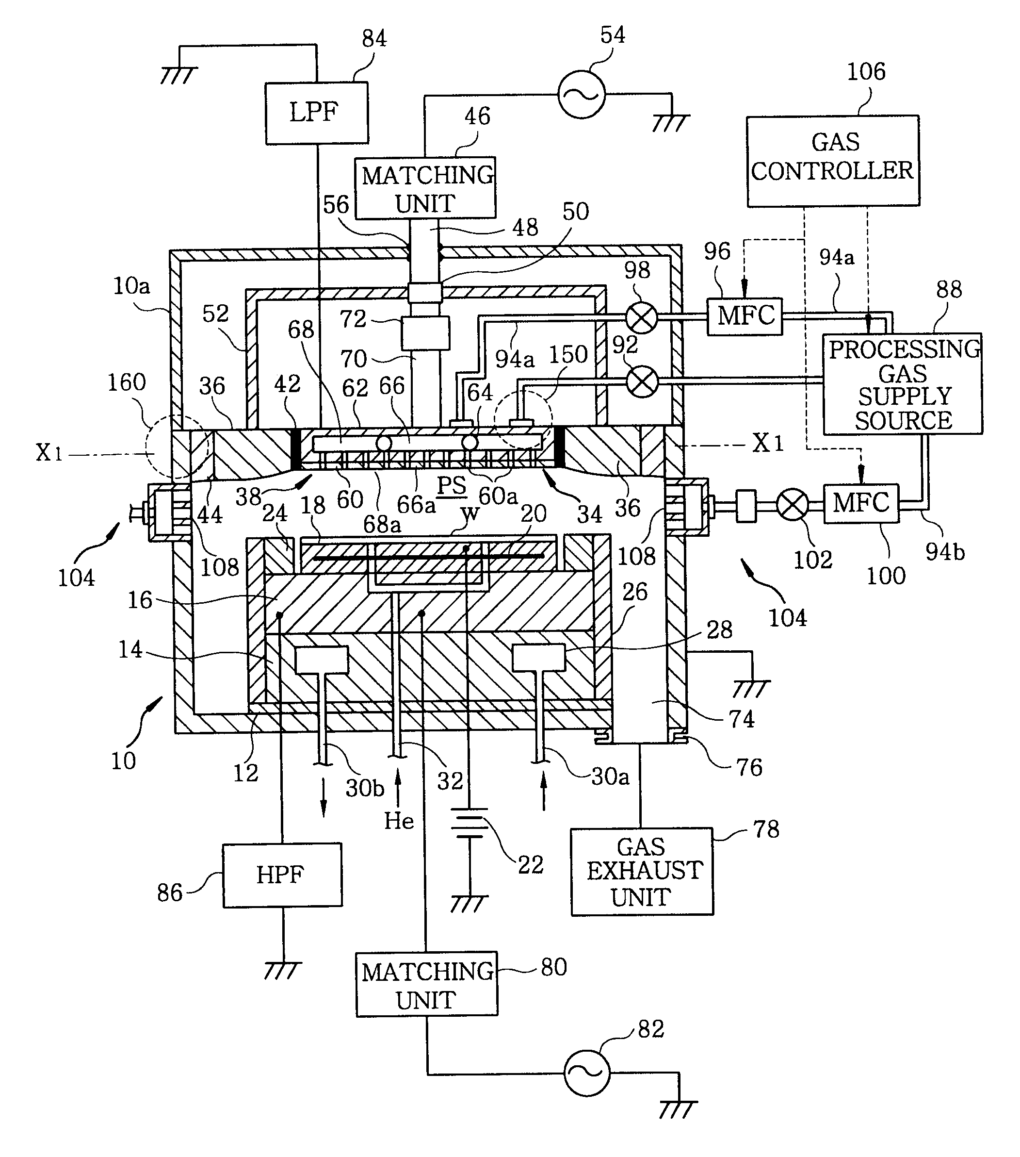
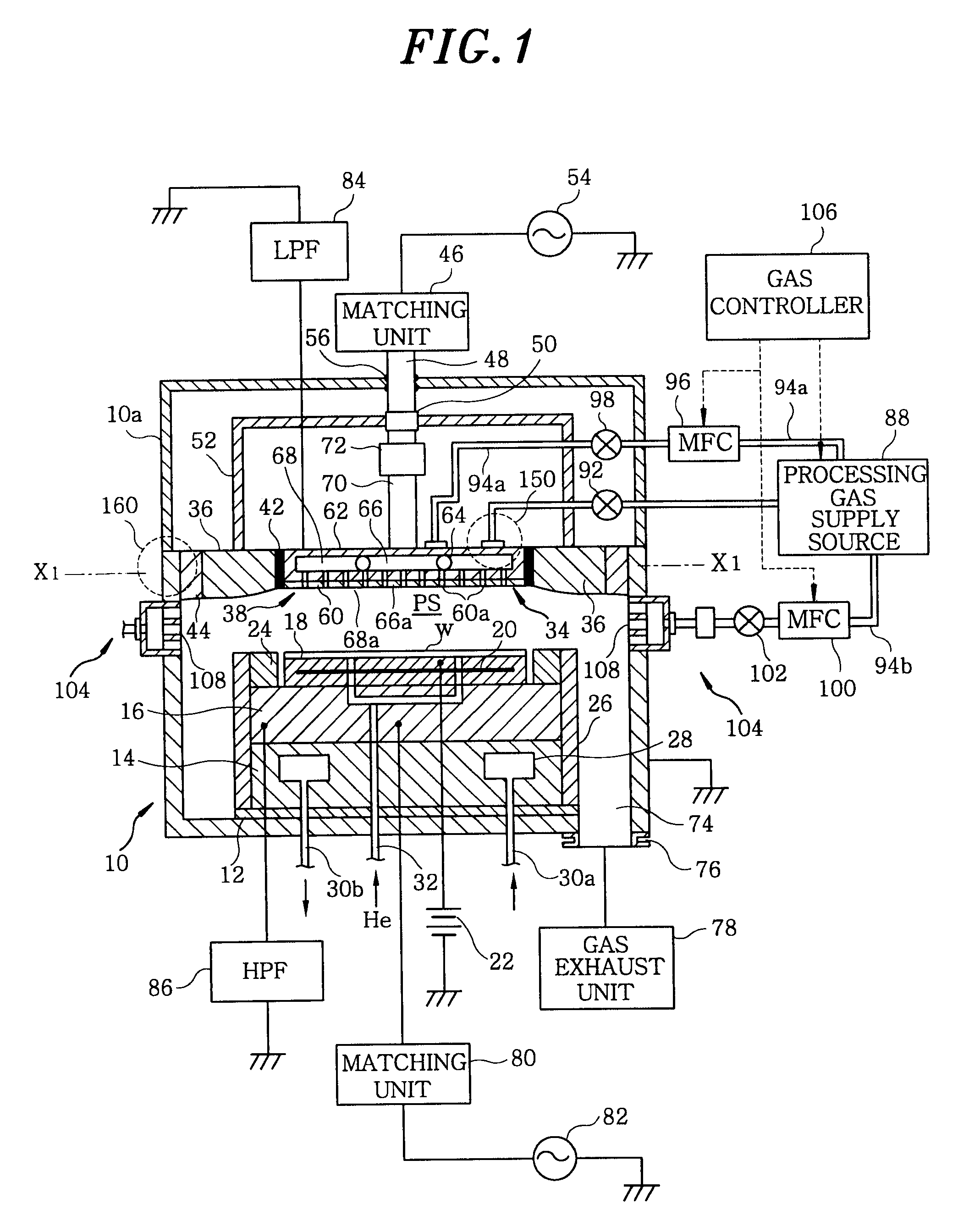
[0080]Hereinafter, there will be described a gas introduction mechanism for introducing a processing gas (etching gas) into the chamber 10 in the plasma etching apparatus. Major features of the gas introduction mechanism in the first embodiment will be described as follows. As a gas inlet for introducing an etching gas into the plasma generation region PS in the chamber 10, there are provided an upper gas inlet (the upper central shower head 66a and the upper peripheral shower head 68a) for introducing a gas through the upper electrode 38 side and a side gas inlet 104 for introducing a gas through the sidewall side of the chamber 10. As illustrated in FIG. 1, the side gas inlet 104 has a side shower head 108 attached to the sidewall of the chamber 10.

[0081]Referring to FIG. 1, a processing gas supply source 88 provides an etchant gas to a gas supply line 90 at a desired flow rate and a dilution gas to a gas supply line 94 at a desired flow rate. The gas supply line 90 communicates w...

second embodiment

[0108]Hereinafter, a gas introduction mechanism of a second preferred embodiment, for introducing a processing gas (an etching gas) into the chamber 10 in the plasma etching apparatus, will be described with reference to FIGS. 9 to 11. A major feature of the gas introduction mechanism in accordance with the second preferred embodiment is that instead of the side gas inlet 104 in the first preferred embodiment, a third upper shower head is provided at an outer portion of the upper peripheral shower head 68a as a gas inlet for introducing an etching gas into the plasma generation region PS in the chamber 10. In other words, the gas introduction mechanism of the second preferred embodiment includes a first upper shower head (the upper central shower head of the first preferred embodiment), a second upper shower head (the upper peripheral shower head of the first preferred embodiment) and the third upper shower head, which are sequentially provided from the central portion of the upper ...


PUM

PropertyMeasurementUnit
thicknessaaaaaaaaaa
diameteraaaaaaaaaa
pressureaaaaaaaaaa

Abstract

A plasma etching method by using a plasma etching apparatus having a depressurizable processing chamber; a lower electrode for mounting thereon a substrate to be processed in the processing chamber; an upper electrode facing the lower electrode in the processing chamber with a plasma generation region formed therebetween; a radio frequency power supply unit for applying a radio frequency power between the upper electrode and the lower electrode to thereby form a radio frequency electric field in the plasma generation region, the method comprising: supplying a first gas including etchant gas to an upper gas inlet to introduce the first gas through the upper electrode into the plasma generation region; and feeding a second gas including dilution gas to a side gas inlet to introduce the second gas through a sidewall of the processing chamber into the plasma generation region.

Description

CROSS-REFERENCE TO RELATED APPLICATIONS[0001]This application is a Continuation application of U.S. patent application Ser. No. 11 / 192,029, filed Jul. 29, 2005, which claims priority to U.S. Provisional applications Ser. No. 60 / 603,547, filed Aug. 24, 2004, and Ser. No. 60 / 635,488, filed Dec. 14, 2004, and Japanese patent applications No. 2004-224274, filed Jul. 30, 2004, and No. 2004-349608, filed Dec. 2, 2004. The entire contents of U.S. patent application Ser. No. 11 / 192,029 are herein incorporated by reference.FIELD OF THE INVENTION [0002]The present invention relates to a plasma etching apparatus; and, more particularly, to a parallel plate plasma etching apparatus.BACKGROUND OF THE INVENTION[0003]A recent trend towards a miniaturized semiconductor device structure in design criteria intensifies a demand for processing a material to be etched in a cross sectional shape of a high-density pattern. Currently, in a plasma etching apparatus for use in manufacturing a semiconductor d...

Claims


Application Information

Patent Timeline
Patent Type & Authority Applications(United States)
IPC IPC(8): C03C15/00
CPCH01J37/32091H01L21/31116H01J37/32449H01J37/3244
Inventor YOSHIDA, RYOICHIYOSHIDA, TETSUOSAITO, MICHISHIGEWAKAKI, TOSHIKATSUAOYAMA, HAYATOOBI, AKIRASUZUKI
Owner TOKYO ELECTRON LTD
Learn More