Motor

Inactive Publication Date: 2010-06-03
NIDEC SANKYO CORP
View PDF4 Cites 15 Cited by
  • Summary
  • Abstract
  • Description
  • Claims
  • Application Information

AI Technical Summary

Benefits of technology

[0011]In view of the problems described above, at least an embodiment of the present invention may advantageously provide

Problems solved by technology

However, its cure time is longer and its linear expansion coefficient under temperature environment is larger and thus it is weak agains

Method used


Image

  • Motor
  • Motor
  • Motor

Examples


first embodiment

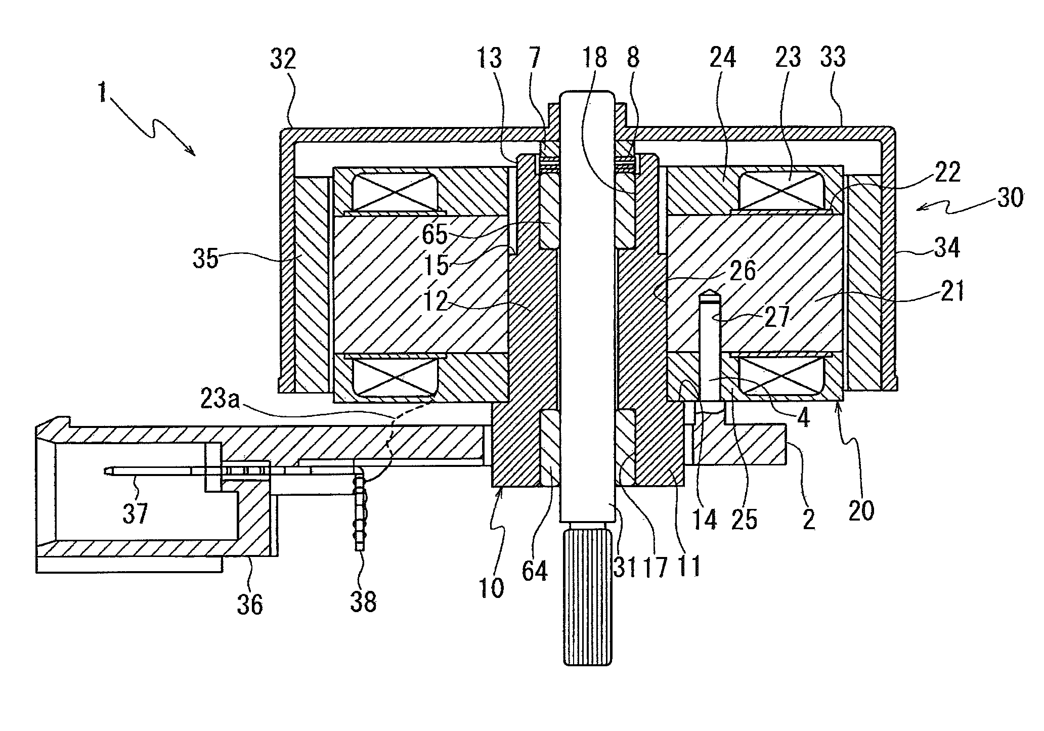
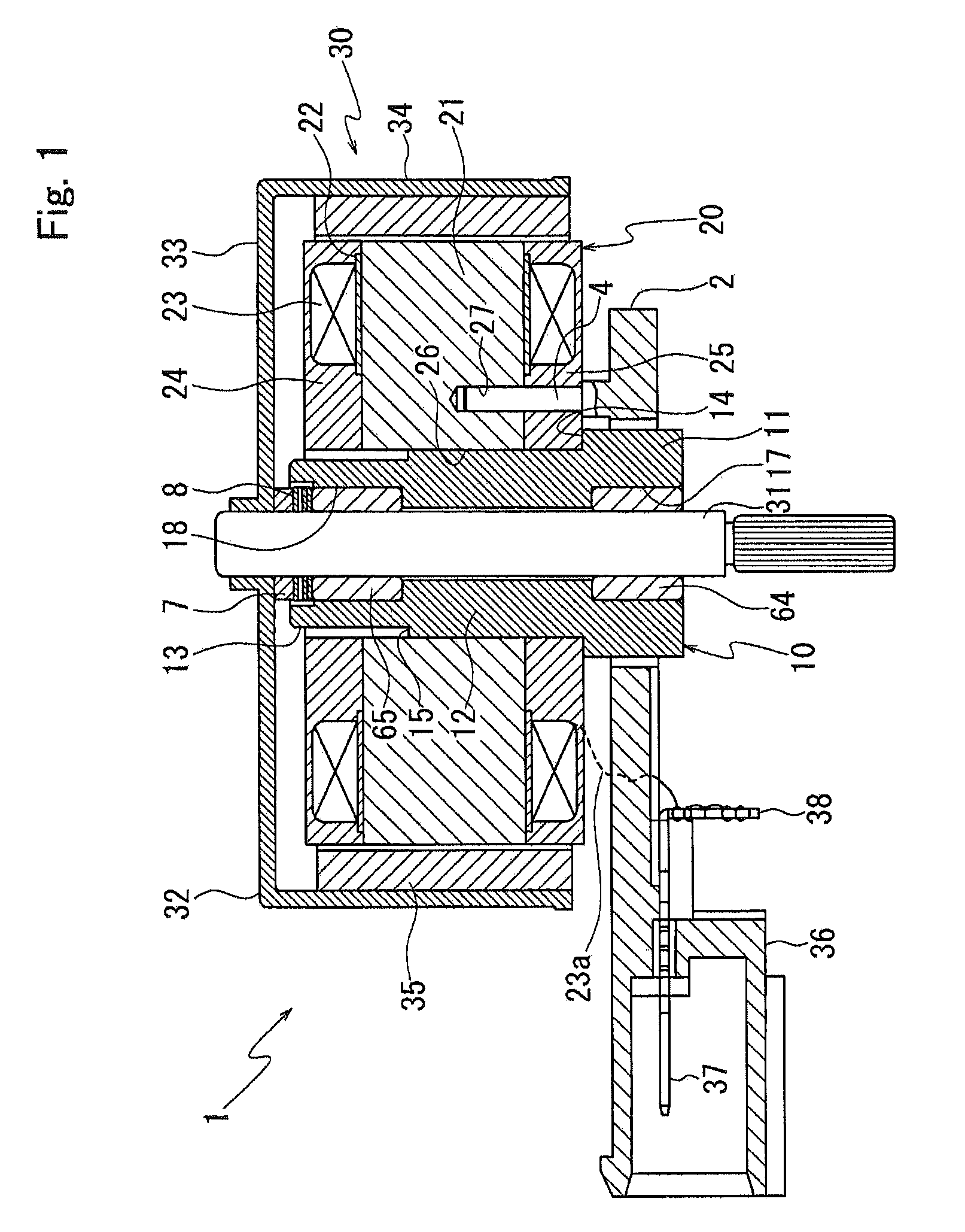
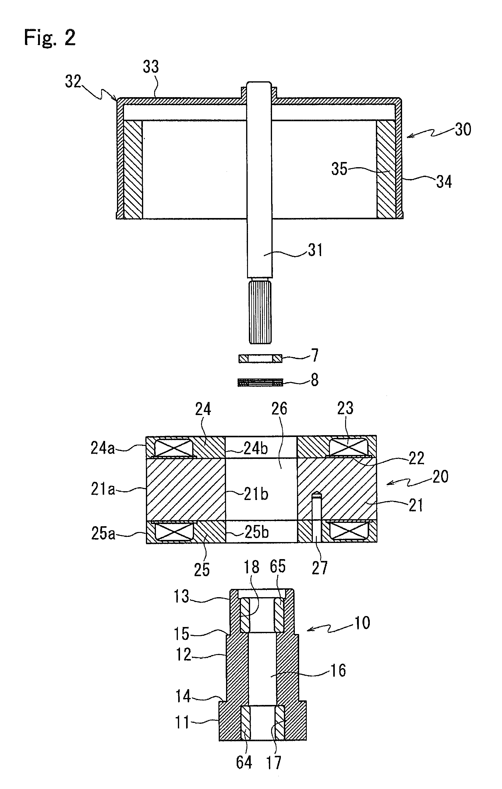
[0030]A motor in accordance with a first embodiment of the present invention will be described in detail below with reference to the accompanying drawings. FIG. 1 is a cross-sectional view showing a motor in accordance with a first embodiment of the present invention and FIG. 2 is its exploded cross-sectional view. In FIG. 2, a motor base plate is not shown.

[0031]A motor 1 is structured so that a stator 20 is press-fitted to a bearing holder 10, a rotor 30 is supported by the bearing holder 10, and the stator 20 is fixed to a motor base plate 2. The stator 20 is structured so that a stator core 21 is covered with an insulation member 22 over a predetermined area, a coil 23 is wound around the insulation member 22, and resin blocks 24 and 25 are molded so as to cover the entire coil 23 with resin on the upper and lower sides of the stator core 21. The insulation member 22 may be a sheet-shaped member which is wound around the stator core 21 or may be a resin molded product which is f...

second embodiment

[0054]Next, a motor in accordance with a second embodiment of the present invention will be described below. In the second embodiment, a stator structure is different from the structure in the first embodiment. FIG. 5 is a cross-sectional view showing a motor in accordance with a second embodiment of the present invention. A basic structure in the second embodiment is similar to that in the first embodiment and thus the same notational symbols are used in the same portions and their descriptions are omitted. Also in the second embodiment, the resin block 25 corresponds to the first resin block and the resin block 24 corresponds to the second resin block. The stepped part 14 corresponds to the stepped part in the second embodiment.

[0055]The stator 20 in the first embodiment is structured so that the stator core 21 is molded so as to be sandwiched by the upper and the lower resin blocks 24 and 25 and so that the inner peripheral face and the outer peripheral face of the stator core 21...


PUM


Abstract

A motor may include a motor base plate, a bearing holder provided with a through hole whose both ends hold bearings and vertically disposed with respect to the motor base plate, a stator provided with a center hole and fixed to an outer peripheral face of the bearing holder, and a rotor having a shaft supported by the bearings, a rotor case fixed to the shaft, and a magnet fixed on an inner peripheral face of the rotor case. The bearing holder may be provided with a stepped part, protruded toward a radial direction. The stator may be provided with a first resin block structured so that an end face on a motor base plate side of the stator core is molded with resin to cover a coil wound around the stator core, and inner peripheral faces of the stator core and the first resin block structure the center hole, and the center hole of the stator is press-fitted and fixed to the bearing holder until an end face of the first resin block is abutted with the stepped part.

Description

CROSS REFERENCE TO RELATED APPLICATION[0001]The present invention claims priority under 35 U.S.C. §119 to Japanese Application No. 2008-304995 filed Nov. 28, 2008, the entire contents of which are incorporated herein by reference.FIELD OF THE INVENTION[0002]An embodiment of the present invention may relate to a motor in which bearings for supporting a rotor is held by a bearing holder and a stator is fixed to the bearing holder.BACKGROUND OF THE INVENTION[0003]A conventional motor has been disclosed, for example, in Japanese Patent Laid-Open No. Hei 10-108404. This motor is structured so that a bearing holder is attached to a motor base plate, bearings are disposed on both ends of a through hole of the bearing holder, and a shaft of a rotor is supported by the bearings. However, a certain space is required to set between an exposed electric wire such as a coil and a metal member around the exposed electric wire through the legal regulations for electrical safety. Therefore, when a c...

Claims


Application Information

Patent Timeline
IPC IPC(8): H02K3/32
CPCH02K1/187H02K7/085H02K5/1675H02K5/08
Inventor HARATA, TAKAJIFUJISHIMA, MAKOTO
Owner NIDEC SANKYO CORP
Why Eureka
Try Eureka