Three-phase dynamoelectrical permanently excited synchronous machine

a dynamoelectric and synchronous machine technology, applied in the direction of dynamo-electric machines, electrical apparatus, magnetic circuit shapes/forms/construction, etc., can solve the problems of permanent magnet breaking, permanent magnets being produced at higher cost, and the magnetic field cannot be arbitrarily thin, so as to reduce the detent and pulsating torque, and the edge of the permanent magnet is lower.

Inactive Publication Date: 2010-06-03
SIEMENS AG
View PDF6 Cites 41 Cited by
  • Summary
  • Abstract
  • Description
  • Claims
  • Application Information

AI Technical Summary

Benefits of technology

[0026]These measures make it possible to lower the edge of the permanent magnets, which contributes to a substantial reduction in the detent and pulsating torques.
[0027]As a result of the cylindrical configuration of the support structure, those permanent magnets whose base radius is identical to the outer radius of the support structure can also be staggered in any desired manner over the axial length of the rotor. The predefinable staggering makes it possible to deliberately mask or reduce harmonics, in particular the fifth and / or seventh harmonic.

Problems solved by technology

However, for reasons of production technology, the permanent magnets cannot be arbitrarily thin in this case in their circumferential edge regions since otherwise there is a risk of the permanent magnets breaking, and this also leads to increased costs when producing the permanent magnets.
However, on account of tolerances of the production means, the desired skew angles cannot be complied with exactly, with the result that detent and pulsating torques still remain.

Method used


Image

  • Three-phase dynamoelectrical permanently excited synchronous machine
  • Three-phase dynamoelectrical permanently excited synchronous machine
  • Three-phase dynamoelectrical permanently excited synchronous machine

Examples


Embodiment Construction

[0045]Throughout all the figures, same or corresponding elements may generally be indicated by same reference numerals. These depicted embodiments are to be understood as illustrative of the invention and not as limiting in any way. It should also be understood that the figures are not necessarily to scale and that the embodiments are sometimes illustrated by graphic symbols, phantom lines, diagrammatic representations and fragmentary views. In certain instances, details which are not necessary for an understanding of the present invention or which render other details difficult to perceive may have been omitted.

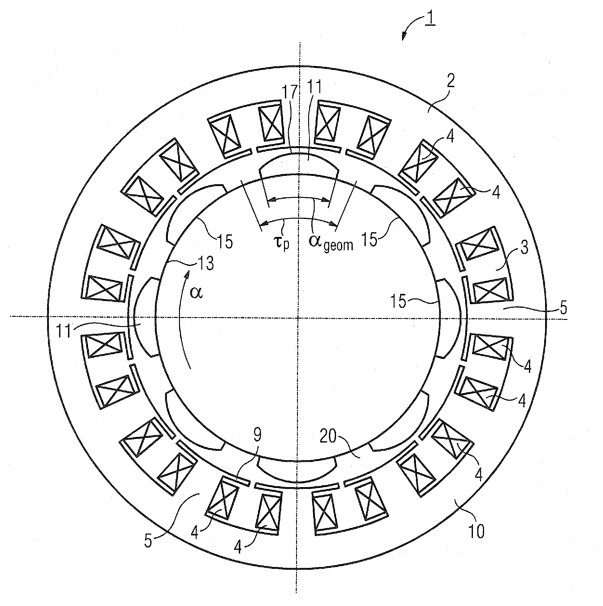
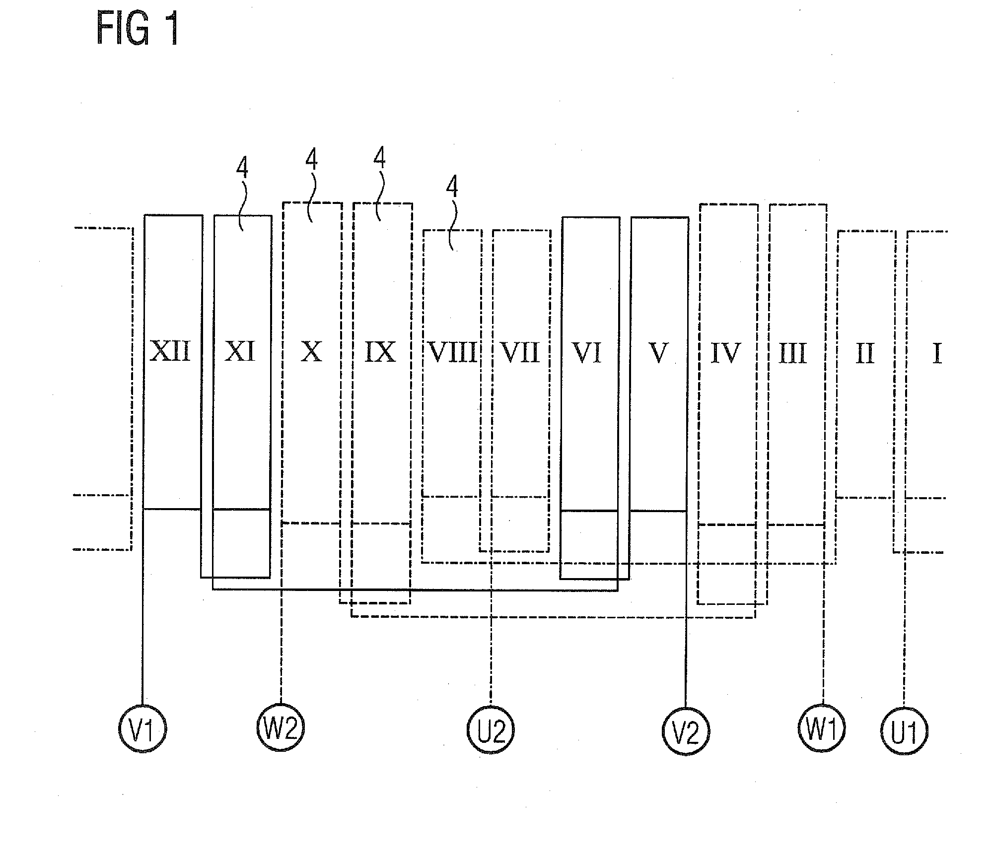
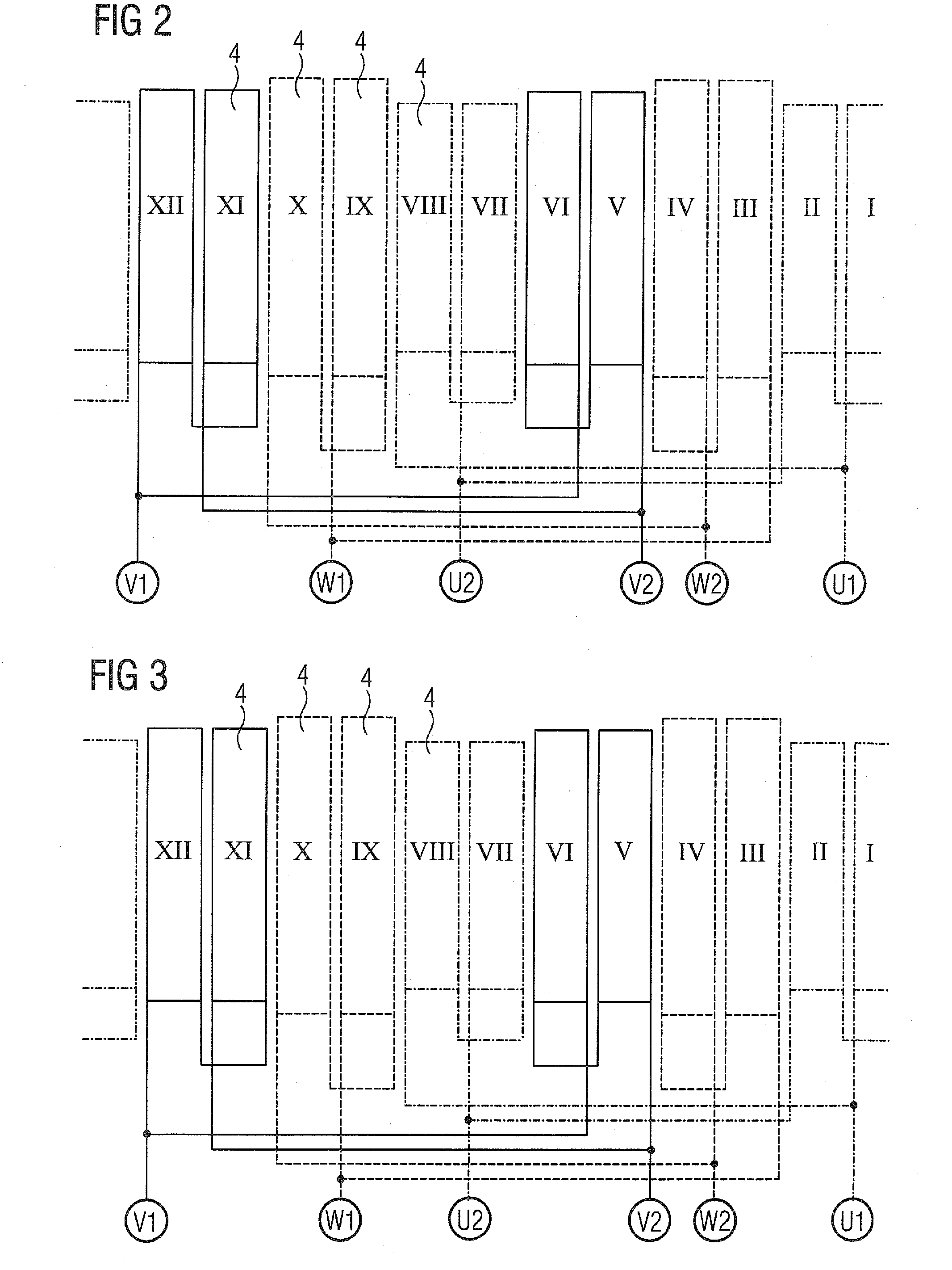
[0046]Turning now to the drawing, and in particular to FIG. 1-3, there are shown circuit diagrams of a three-phase U, V, W stator 2 of a permanently excited synchronous machine 1 with twelve slots 3, which stator is provided with a winding system which has tooth-wound coils 4 in the present exemplary embodiment. Each tooth-wound coil 4 comprises a tooth 5 of the stator 2 in ...


PUM


Abstract

A three-phase dynamoelectrical permanently excited synchronous machine includes a stator with teeth which point to a rotor, wherein twelve slots are formed between the teeth. The slots have coil sides of coils of a winding system in such a manner that two coil sides of different coils are situated in each slot. The rotor has a cylindrical support structure which is provided with permanent magnets defined by an inner radius which corresponds to a radius of the support structure, and by an outer radius which is smaller than their inner radius. The permanent magnets are formed with ten magnet poles when viewed in a circumferential direction.

Description

CROSS-REFERENCES TO RELATED APPLICATIONS[0001]This application claims the priority of European Patent Application, Serial No. EP 08020838, filed Dec. 1, 2008, pursuant to 35 U.S.C. 119(a)-(d), the content of which is incorporated herein by reference in its entirety as if fully set forth herein.BACKGROUND OF THE INVENTION[0002]The present invention relates to a three-phase dynamoelectrical permanently excited synchronous machine having a stator with teeth which point to a rotor which has permanent magnets.[0003]The following discussion of related art is provided to assist the reader in understanding the advantages of the invention, and is not to be construed as an admission that this related art is prior art to this invention.[0004]Dynamoelectrical synchronous machines which are excited using permanent magnets, in particular permanent magnets of constant thickness, ideally have a rectangular exciter field. The harmonics contained in the rectangular field now lead, with the harmonics ...

Claims


Application Information

Patent Timeline
Patent Type & Authority Applications(United States)
IPC IPC(8): H02K1/17
CPCH02K1/278H02K29/03H02K21/16H02K3/28H02K1/2781
Inventor GROSSMANN, UDOSCHUNK, HOLGERVOLLMER, ROLFZASTROW, MICHAEL
Owner SIEMENS AG
Why Eureka
Try Eureka