
Battery system with practical voltage detection

a battery system and voltage detection technology, applied in the field of battery systems, can solve the problems of significant degradation of over-charged or over-discharged battery cells, inability to maintain the voltage and remaining capacity of all battery cells, and over-charging or over-discharging of certain battery cells, so as to accurately measure the voltage of the battery cell.

Inactive Publication Date: 2010-06-03
SANYO ELECTRIC CO LTD
View PDF4 Cites 46 Cited by
  • Summary
  • Abstract
  • Description
  • Claims
  • Application Information

AI Technical Summary

Benefits of technology

[0011]The battery system described above has the characteristic that it can judge via the decision circuit whether or not the voltage detection circuit can accurately measure battery cell voltage, and it can accurately measure battery cell voltage with a voltage detection circuit confirmed to operate properly. This is because the decision circuit can detect abnormal connection between a battery cell and the voltage detection circuit from battery cell discharge voltage or from the difference between battery cell non-discharge voltage and discharge voltage.

Problems solved by technology

For a battery system having a plurality of battery cells connected in series, although each battery cell is charged and discharged with the same current, the voltage and remaining capacity of all battery cells cannot be maintained equal because of battery cell electrical characteristics are not uniform.
Battery cell voltage and remaining capacity imbalance results in over-charging or over-discharging of certain battery cells.
This condition causes significant degradation of the over-charged or over-discharged battery cells.
This is because over-charging and over-discharging cause remarkable degradation in battery cell electrical characteristics.
Further, battery cell voltage rise due to over-charging is also a cause of reduced battery safety.
However, if the voltage detection circuit that detects battery cell voltage becomes unable to properly measure battery cell voltage, battery cell voltage imbalance cannot be corrected.
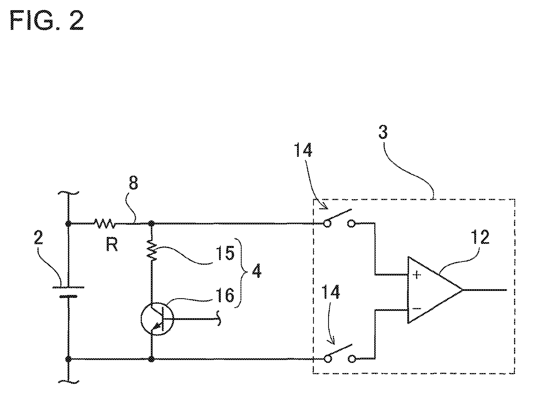
Consequently, as contact resistance increases, the battery cell voltage input to the voltage detection circuit becomes abnormal.
As contact resistance increases relative to the input impedance, detection error increases.
However, if voltage detection circuit input impedance is made large, the circuit becomes easily affected by noise, and it becomes difficult to accurately measure battery cell voltage.
Therefore, detection error due to even a small amount of contact resistance can be a cause of battery cell degradation.
Since this is a condition where an over-charged battery cell with high voltage cannot be discharged, it is a cause of reduced battery system safety.
Further, although detection error due to wire-lead contact resistance can be reduced by increasing the input impedance of the voltage detection circuit, degradation of the input isolation resistance of a high input impedance voltage detection circuit can also be the cause of voltage detection error.
Consequently, when the input-side isolation resistance of the voltage detection circuit decreases, battery cell voltage cannot be accurately measured.
Since a decrease in isolation resistance reduces the detected voltage of a battery cell, it becomes impossible to discharge a high voltage battery cell with a tendency to over-charge, and this also is a cause of reduced battery system safety.

Method used


Image

  • Battery system with practical voltage detection
  • Battery system with practical voltage detection
  • Battery system with practical voltage detection

Examples


Embodiment Construction

)

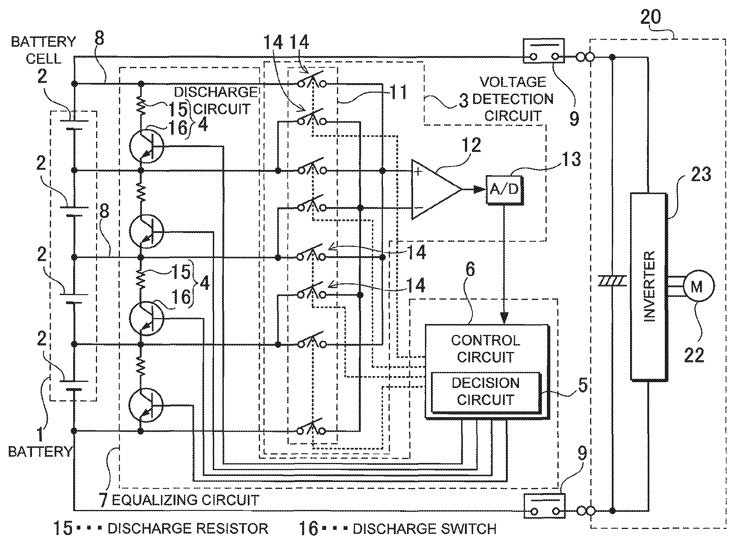
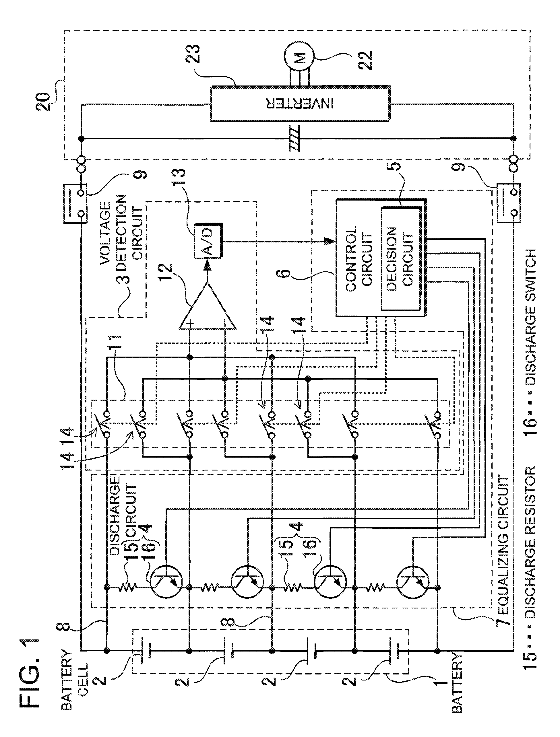
[0017]The discharge circuits 4 of the battery system can form an equalizing circuit 7 that corrects voltage imbalance in the series-connected battery cells 2. In this battery system, since the equalizing circuit is used to determine whether or not battery cell voltage is correctly input to the voltage detection circuit, it is unnecessary to provide a special-purpose discharging circuit just to measure battery cell discharge voltage. Consequently, abnormal connection between a battery cell and the voltage detection circuit can be detected with a simple circuit structure.

[0018]Each discharge circuit 4 of the battery system can be provided with a series-connected discharge resistor 15 and discharge switch 16.

[0019]The decision circuit 5 of the battery system can control the discharge switches 16 of the discharge circuits 4 to detect battery cell 2 discharge voltage. In this battery system, since the discharge switches are controlled by the decision circuit, whether or not the voltage ...


PUM


Abstract

The battery system has a battery 1 having a plurality of series-connected battery cells 2, a voltage detection circuit 3 that detects each battery cell voltage, discharge circuits 4 to discharge each battery cell, and a decision circuit 5 that judges the condition of the connection between a battery cell 2 and the voltage detection circuit 3 from the detected battery cell voltage measured by the voltage detection circuit. The voltage detection circuit 3 measures discharge voltage of a battery cell 2 with the discharge circuit 4 in the discharging state, and measures non-discharge voltage with the battery cell 2 in a non-discharging state. The decision circuit 5 compares the difference between the detected battery cell non-discharge voltage and discharge voltage with the normal voltage, or compares battery cell discharge voltage with the normal voltage to judge abnormal connection between the battery cell and the voltage detection circuit.

Description

BACKGROUND OF THE INVENTION[0001]1. Field of the Invention[0002]The present invention relates to a battery system optimized for use as a car power source apparatus that supplies power to a motor that drives the vehicle.[0003]2. Description of the Related Art[0004]A battery system having many series-connected rechargeable battery cells, such as lithium ion batteries, detects the voltage of each battery cell to control battery charging and discharging. This is because prevention of over-charging and over-discharging allows battery cell lifetime to be extended while safely charging and discharging the battery cells. For a battery system having a plurality of battery cells connected in series, although each battery cell is charged and discharged with the same current, the voltage and remaining capacity of all battery cells cannot be maintained equal because of battery cell electrical characteristics are not uniform. Battery cell voltage and remaining capacity imbalance results in over-c...

Claims


Application Information

Patent Timeline
Patent Type & Authority Applications(United States)
IPC IPC(8): H02J7/00G01R31/36H02J7/02
CPCH02J7/0026H02J7/0021H02J7/0048H02J7/0016H02J7/0029
Inventor OOSAWA, TAKESHIFURUKAWA, KIMIHIKO
Owner SANYO ELECTRIC CO LTD
Learn More