Polymer electrolyte fuel cell and fuel cell sealing member for the same
a technology of electrolyte fuel cell and sealing member, which is applied in the direction of electrochemical generators, cell components, cell component details, etc., can solve the problems of extreme difficulty in maintaining efficient power generation performance, and achieve the effect of ensuring sufficient power generation performance, simple constitution and sufficient power generation
- Summary
- Abstract
- Description
- Claims
- Application Information
AI Technical Summary
Benefits of technology
Problems solved by technology
Method used
Image
Examples
first embodiment
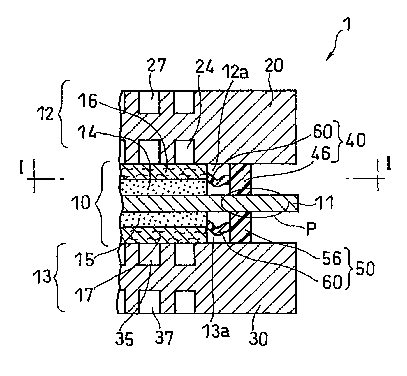
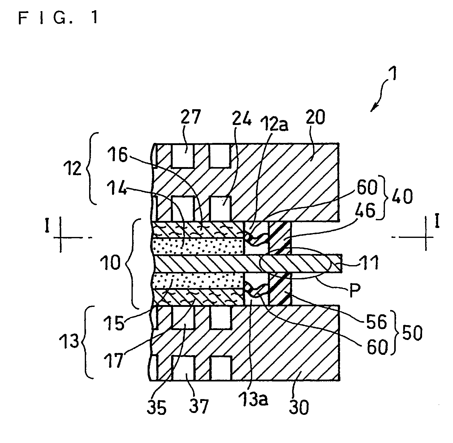
[0043]FIG. 1 shows a cross sectional view of a relevant part of a basic component (unit cell) of a polymer electrolyte fuel cell of the present invention. As shown in FIG. 1, a fuel cell 1 includes at least one unit cell composed mainly of a membrane electrode assembly (MEA) 10, and a pair of separator plates sandwiching the membrane electrode assembly 10, specifically, an anode-side separator 20 and a cathode-side separator 30.
[0044]The membrane electrode assembly 10 has a constitution in which a polymer electrolyte membrane 11 that selectively transports cations (hydrogen ions) is disposed between the anode 12 and the cathode 13. Further, the anode 12 includes at least a catalyst layer 14 disposed in tight contact with the polymer electrolyte membrane 11 and a gas diffusion layer 16 disposed between the catalyst layer 14 and the anode-side separator 20. The cathode 13 includes at least a catalyst layer 15 disposed in tight contact with the polymer electrolyte membrane 11 and a gas...
second embodiment
[0068]A polymer electrolyte fuel cell according to a second embodiment of the present invention will now be described. In this fuel cell according to the second embodiment (not shown), the anode-side sealing member and the cathode-side sealing member are configured differently from those of the fuel cell 1 of the first embodiment shown in FIG. 1, so the fuel cell according to the second embodiment has the same constitution as that of the fuel cell 1 according to the first embodiment except for the anode-side sealing member and the cathode-side sealing member.
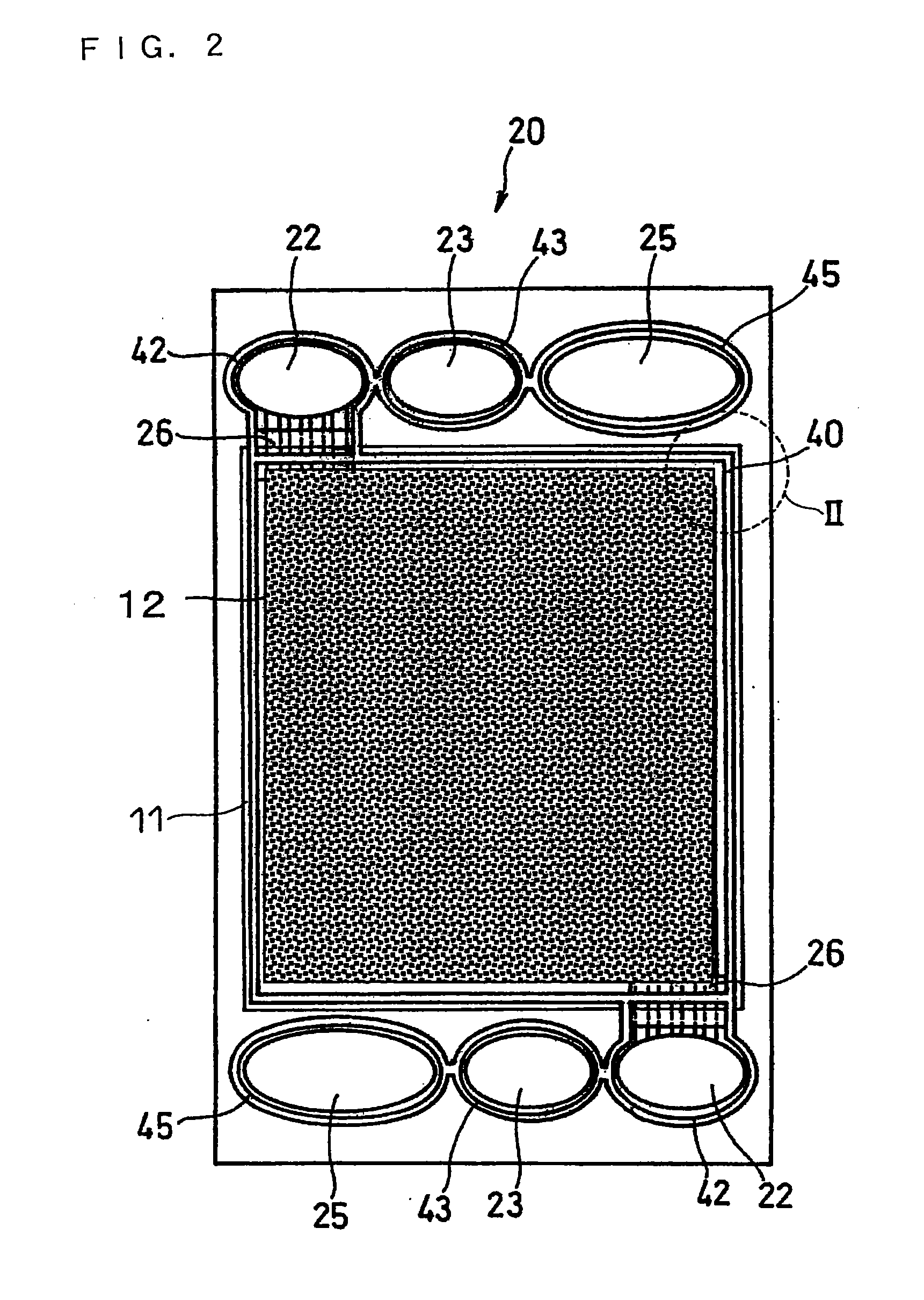
[0069]Hereinafter, the anode-side sealing member included in the fuel cell of the second embodiment will be described. FIG. 4 is an enlarged view of a relevant part of the portion indicated by “II” of FIG. 2, that is, a diagram to illustrate the structure of the anode-side sealing member 40 of the fuel cell according to the second embodiment.
[0070]As shown in FIG. 4, the anode-side sealing member 40 of this embodiment comprises ...
third embodiment
[0074]A polymer electrolyte fuel cell according to a third embodiment of the present invention will now be described. In this fuel cell according to the third embodiment (not shown), the anode-side sealing member and the cathode-side sealing member are configured differently from those of the fuel cell 1 of the first embodiment shown in FIG. 1, so the fuel cell according to the third embodiment has the same constitution as that of the fuel cell 1 according to the first embodiment except for the anode-side sealing member and the cathode-side sealing member.
[0075]Hereinafter, the anode-side sealing member included in the fuel cell of the third embodiment will be described. FIG. 5 is an enlarged view of a relevant part of the portion indicated by “II” of FIG. 2, that is, a diagram to illustrate the structure of the anode-side sealing member 40 of the fuel cell according to the third embodiment.
[0076]As shown in FIG. 5, the anode-side sealing member 40 of this embodiment comprises an an...
PUM
| Property | Measurement | Unit |
|---|---|---|
| size | aaaaa | aaaaa |
| thickness | aaaaa | aaaaa |
| size | aaaaa | aaaaa |
Abstract
Description
Claims
Application Information
 - R&D
- Intellectual Property
- Life Sciences
- Materials
- Tech Scout
- Unparalleled Data Quality
- Higher Quality Content
- 60% Fewer Hallucinations
Browse by: Latest US Patents, China's latest patents, Technical Efficacy Thesaurus, Application Domain, Technology Topic, Popular Technical Reports.
© 2025 PatSnap. All rights reserved.Legal|Privacy policy|Modern Slavery Act Transparency Statement|Sitemap|About US| Contact US: help@patsnap.com


