

Fuel cell and fuel cell stacks equipped with this
Patent Information
- Authority / Receiving Office
- CN · China
- Patent Type
- Applications(China)
- Current Assignee / Owner
- PANASONIC CORP
- Publication Date
- 2007-05-02
- Estimated Expiration
- Not applicable · inactive patent
Smart Images
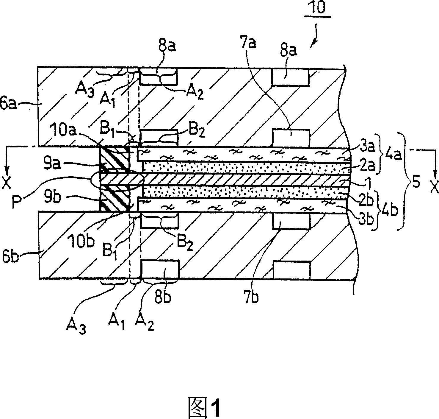
Figure 1 
Figure 2 
Figure 3
Abstract
Description
technical field
[0001] The present invention relates to a fuel cell (in particular, to a polymer electrolyte fuel cell), and a fuel cell stack including the fuel cell. Background technique
[0002] A polymer electrolyte fuel cell is a battery that simultaneously generates electricity and heat by electrochemically reacting a fuel gas such as hydrogen and an oxidizing gas such as air with each other at gas diffusion electrodes serving as positive and negative electrodes. Fig. 22 shows a typical structure of such a polymer electrolyte fuel cell. As shown in FIG. 22, the fuel cell 100 includes at least one unit cell (cell) mainly composed of a membrane electrode assembly (MEA) 105 and a pair of separators sandwiching the membrane electrode assembly 105, that is, positive electrode side separators 106a. and the negative side separator 106b.
[0003] Membrane electrode assembly 105 has a structure in which polymer electrolyte membrane 101 that selectively transports cations (hyd...