Power generation material, power generation element, and power generation system

a power generation element and power generation technology, applied in thermoelectric device junction materials, inorganic chemistry, chemistry apparatus and processes, etc., can solve the problems of inability to obtain sufficient power generation performance, inability to use high-temperature heat sources, and large amounts of thermal energy emitted and lost in the form of exhaust heat and light, etc., to achieve the effect of sufficient power generation performan

Inactive Publication Date: 2016-08-04
DAIHATSU MOTOR CO LTD +1
View PDF0 Cites 0 Cited by
  • Summary
  • Abstract
  • Description
  • Claims
  • Application Information

AI Technical Summary

Benefits of technology

[0013]The power generation element including the power generation material, and the power generation system provided with the power generation element can provide sufficient power generation performance even in a high temperature range (for example, 315° C. or higher).
[0014]The objects, features, aspects, and advantages of the present invention will become apparent from the following detailed description and the attached drawings.

Problems solved by technology

Typically, large amounts of thermal energy are emitted and lost in the form of exhaust heat and light, for example, in various energy utilizing devices, such as internal combustion engines including automobile engines; heat exchangers including boilers and air conditioning equipment; electric engines including electric generators and motors; and light-emitting devices for illumination and the like.
However, the Curie point of the Nb and Sn-added PZT (Nb / Sn / Pb(Zr,Ti)O3) described in the cited Patent Document 1 is 315° C. In temperature ranges above the Curie point, sufficient power generation performance cannot be obtained.
As a result, it may not be possible to use a high-temperature heat source.

Method used


Image

  • Power generation material, power generation element, and power generation system
  • Power generation material, power generation element, and power generation system
  • Power generation material, power generation element, and power generation system

Examples


example 1

[0160]A powder of K2CO3, a powder of Na2CO3, and a powder of Nb2O5 were compounded to achieve the molar ratios of K2CO3:Na2CO3:Nb2O5=1:1:2. The powders were stirred and mixed with ion-exchanged water in a wet-type ball mill (from Nikkato Corporation) using zirconia balls for 24 hours, and then dried.

[0161]The obtained powder was heated in air at a temperature-increase rate of 5° C. / min. The powder was heat-treated at 880° C. for 4 hours, mixed and pulverized in a dry-type ball mill (from Nikkato Corporation) using zirconia balls for 12 hours.

[0162]Then, polyvinyl alcohol as a binder was added to be 0.04 part by mass relative to a total amount of 100 parts by mass of the powder after heat treatment and the polyvinyl alcohol. This was followed by stirring and mixing in the wet-type ball mill for 2 hours.

[0163]The resultant mixture was then poured into a mold. Using a hot-press device (from Fujidempa Kogyo Co., Ltd.), heating (hot-pressing) was performed at 60 MPa and 1100° C. for 2 ho...

example 2

[0165]A power generation material including (K1 / 2Na1 / 2)NbO3 and a power generation element including the power generation material were obtained by the same method as in Example 1 with the exception that, instead of the hot-press device, a spark plasma sintering machine (from SPS Syntex Inc.) was used, and that the molding was obtained by heating at 50 MPa and 920° C. for 5 minutes, using pulse electric current sintering method.

Evaluation

1. Composition Analysis

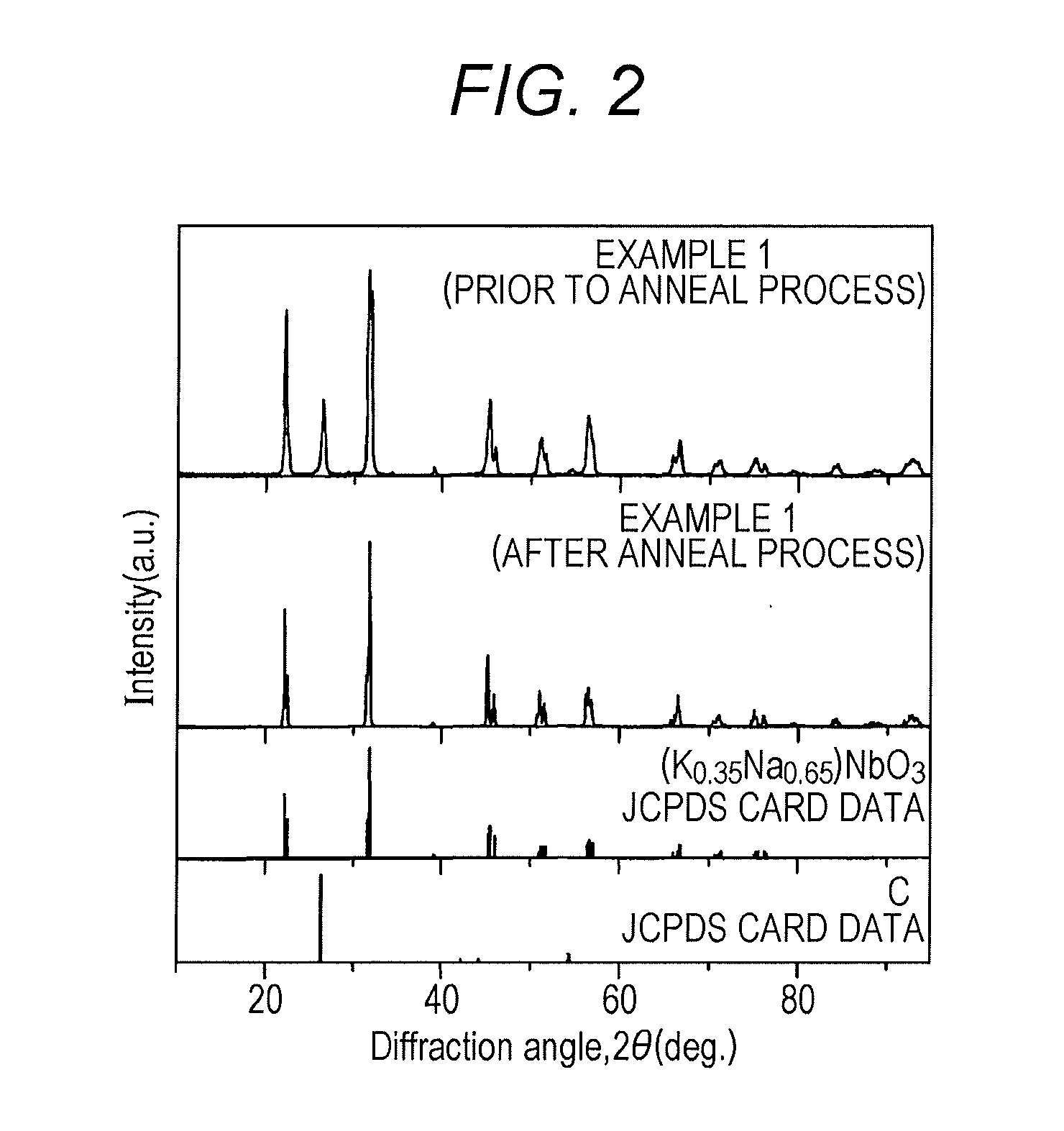
[0166](1) The power generation element obtained in Example 1 was measured using an X-ray diffraction (XRD) device. The power generation element according to Example 1 was measured before and after the anneal process. The obtained XRD data are shown in FIG. 2 together with the JCPDS card data of carbon (C) and (K0.65Na0.35)NbO3.

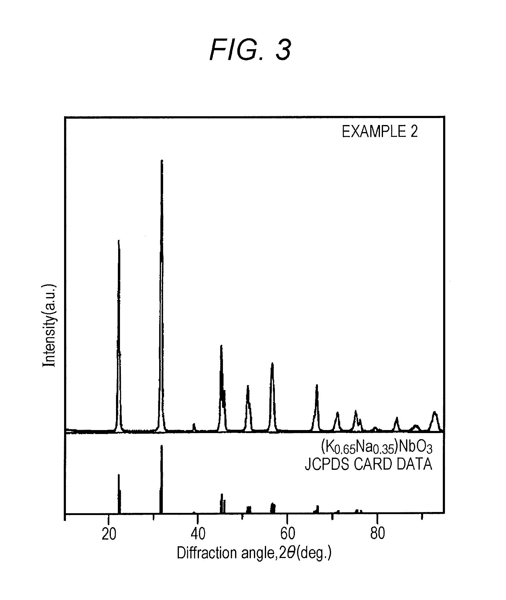
[0167]The power generation element obtained in Example 2 was also measured using the X-ray diffraction device. The obtained XRD data are shown in FIG. 3 together with the JCPDS card data of (K0.65Na0.35)...


PUM

PropertyMeasurementUnit
Curie pointaaaaaaaaaa
temperatureaaaaaaaaaa
Curie pointaaaaaaaaaa

Abstract

Provided are a power generation element including a power generation material indicated by the following general formula (1), and a power generation system using the power generation element: (AxB1-x)NbO3 (1), where A and B are mutually different and represent at least one element selected from rare-earth elements, alkaline-earth metals, alkaline metals, Cd, and Bi, and x represents an atomic proportion in a numerical range of 0<x≦1. The configuration provides a power generation material that enables sufficient power generation performance even in a high temperature range, a power generation element including the power generation material, and a power generation system using the power generation element.

Description

TECHNICAL FIELD[0001]The present invention relates to a power generation material, a power generation element, and a power generation system. Specifically, the present invention relates to a power generation material, a power generation element including the power generation material, and a power generation system using the power generation element.BACKGROUND ART[0002]Typically, large amounts of thermal energy are emitted and lost in the form of exhaust heat and light, for example, in various energy utilizing devices, such as internal combustion engines including automobile engines; heat exchangers including boilers and air conditioning equipment; electric engines including electric generators and motors; and light-emitting devices for illumination and the like.[0003]In recent years, there is growing demand to collect and reuse the emitted thermal energy as an energy source, from the viewpoint of energy conservation.[0004]For example, one specific method proposes a power generation ...

Claims


Application Information

Patent Timeline
Patent Type & Authority Applications(United States)
IPC IPC(8): H01L35/22C01G33/00
CPCC01G33/006C01P2002/72H01L35/22H01L37/025C01P2004/03H10N10/855H10N15/15
Inventor KIM, JUYOUNGKIM, YOONHOOGAWA, TAKASHIYAMANAKA, SATORUNAKAJIMA, AKIRATANAKA, HIROHISANAKAYAMA, TADACHIKATAKEDA, MASATOSHIYAMADA, NOBORUNIIHARA, KOICHI
Owner DAIHATSU MOTOR CO LTD
Why Eureka
Try Eureka