
Intravascular needle and catheter assembly

a catheter and needle technology, applied in the field of intravascular needles and catheter assemblies, can solve the problems of considerable pain and anxiety for patients, significant failure rate of experienced and skilled practitioners, and difficulty in ensuring the safety of patients, so as to minimize potential damage

Inactive Publication Date: 2010-06-03
DARTMOUTH HITCHCOCK CLINIC
View PDF19 Cites 5 Cited by
  • Summary
  • Abstract
  • Description
  • Claims
  • Application Information

AI Technical Summary

Benefits of technology

[0010]This invention overcomes the disadvantages of the prior art by providing an improved intravascular needle and catheter arrangement for use in arterial and intravenous (IV) insertions that ensures flashback is indicated after the catheter is safely inserted through the needle puncture in the vascular wall and emplaced into the vessel. This placement location, at which flashback first occurs is sufficient to begin threading the catheter without risk of over-insertion or under-insertion. The geometry of the needle tip, while providing a sharpened point that minimizes insertion pain and increases the chance of success, also reduces the chance of damage to the back wall of the vessel, should over-insertion occur. In an illustrative embodiment, the catheter compromises a flexible polymeric shaft that flexibly overlies a needle having a distal tip that defines a point. The needle tip includes an enclosed distal-most end and a port located along at least one of the proximal portion of the point and an adjacent cylindrical sidewall of the needle. The distal end of the catheter is constructed and arranged so as to expose the port for entry of blood from a vessel thereinto only after the distal end of the catheter has entered sufficiently into the interior of the vessel for threading. The point is disposed at or near a central axis of the needle shaft, with the port disposed on a first side of the tip and an opposing second side of the tip defining a generally curved surface, or heel, that allows the tip to be deflected along the back wall of the vessel in the event of over-insertion, rather than puncturing it.
[0012]A medical treatment procedure employing the above-described needle is also provided. This procedure allows for detection of full insertion via the observed flashback and minimizes potential damage to the inner vessel wall opposite the puncture side of the vessel based upon the curved / rounded heel described herein.

Problems solved by technology

However these procedures require substantial skill for success, and even experienced and skilled practitioners have exhibited significant failure rates.
This results in considerable pain and anxiety for the patient, who may have to endure multiple attempts to insert the catheter.
Most insertion failures appear to occur at a discrete point in this multi-step procedure.
Beginners often fail to appreciate that when the flashback of blood occurs for the clinician to observe, the needle tip (and orifice) are in the vein or artery, but the catheter tip, which overlies the needle, has not yet entered the vessel.
Thus, an inexperienced or inattentive clinician may attempt to thread the catheter immediately upon such flashback.
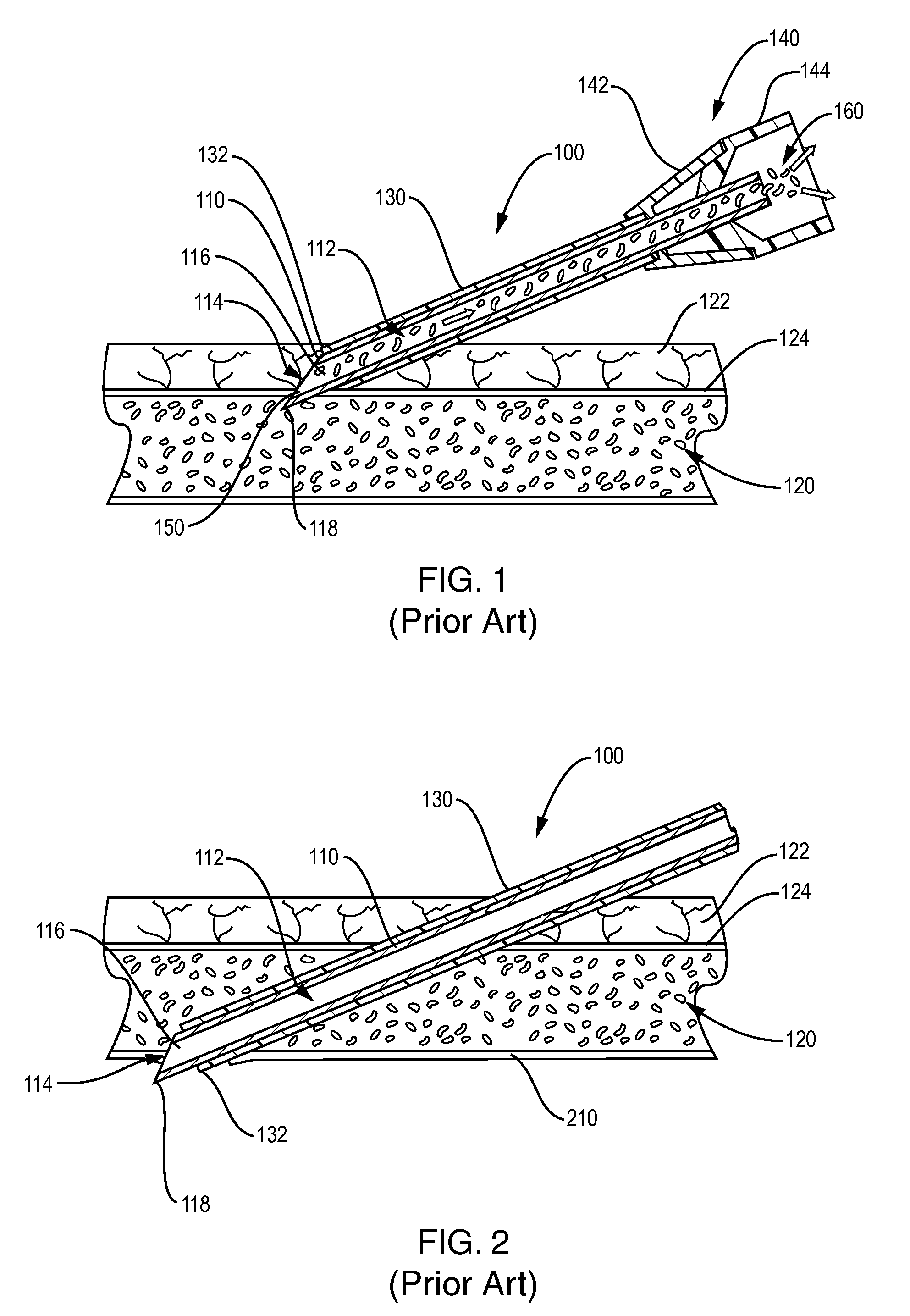
Unfortunately, as shown in FIG. 2, during this additional-distance insertion, the sharp, beveled point 118 on the distal tip of the needle 110 often penetrates the opposite or back wall 210 of the vessel 120 resulting in failure and a painful hematoma.
However, the use of a solid tip dictates that the needle be inserted a significant distance into the vessel before any flashback occurs.
This degree of insertion may, in fact be excessive.
Moreover, the traditional beveled tip does nothing to reduce the damage potential from an over-penetrating insertion.

Method used


Image

  • Intravascular needle and catheter assembly
  • Intravascular needle and catheter assembly
  • Intravascular needle and catheter assembly

Examples


Embodiment Construction

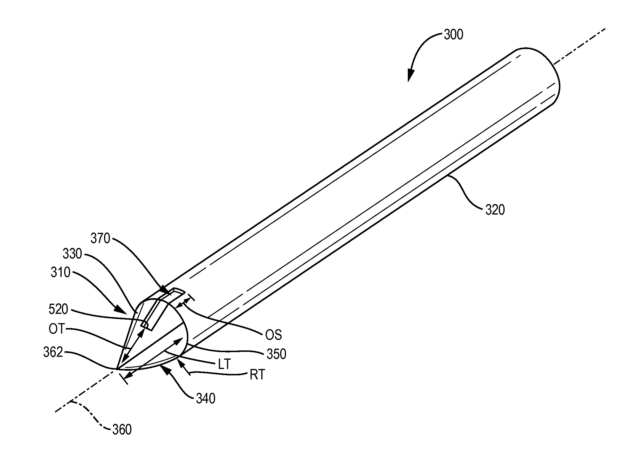
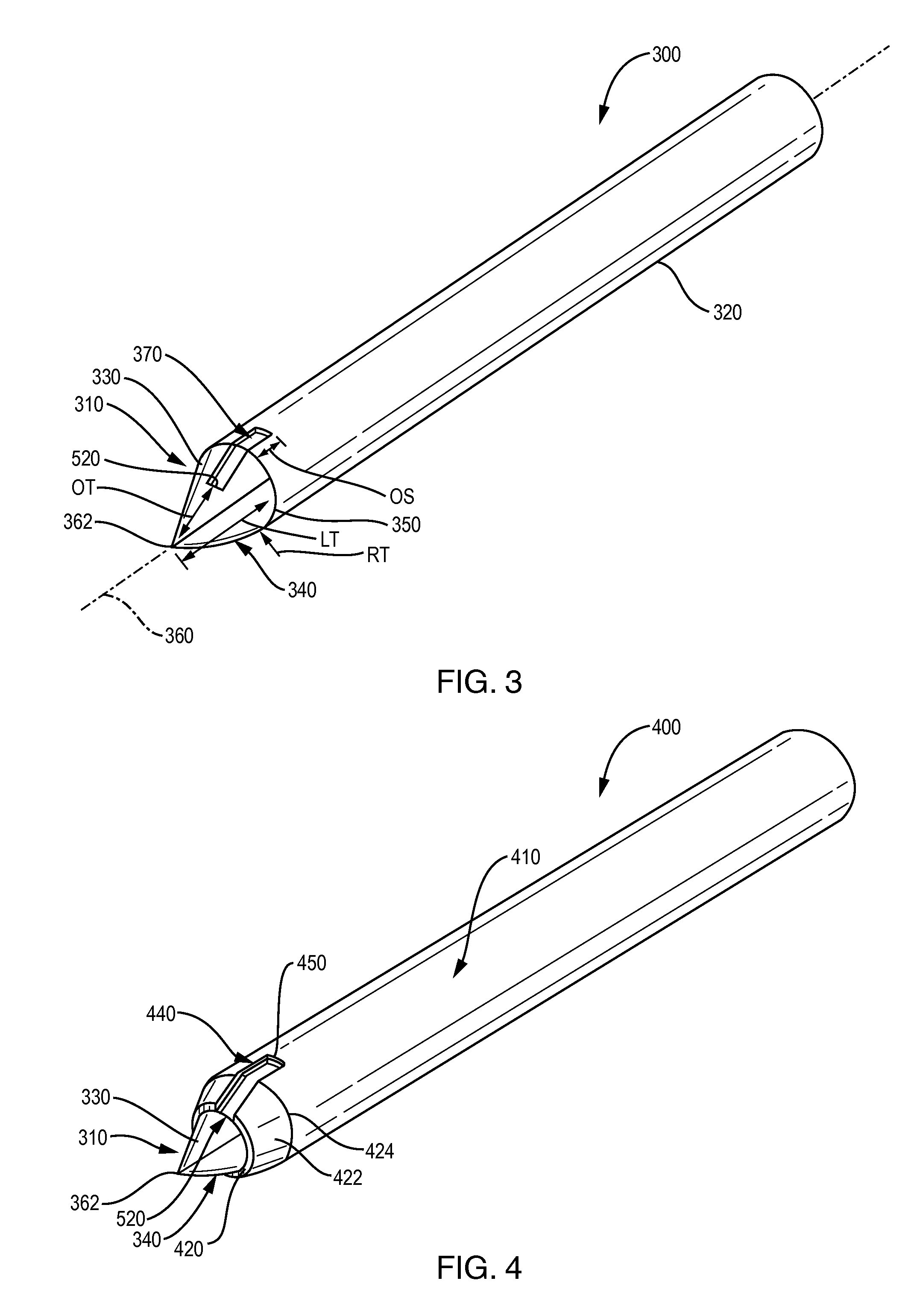
[0032]FIG. 3 shows an insertion needle 300 having a distal tip according to an illustrative embodiment. The tip 310 is formed on the distal end of the needle shaft 320. The shaft 320 in this embodiment defines a cylinder sized in an appropriate diameter (14-24 G, for example) for use in an arterial or IV insertion application. The needle is constructed from a suitable metal or other biocompatible material, such as stainless steel. The tip 310 can be formed by a variety of techniques as described above. For example, the tip can be built up using weldments and / or solder on the end of a cylindrical needle shaft. The shaft end can also be formed into the depicted tip using a swaging or similar plastic deformation technique. The tip can alternatively comprise a separate unit that is affixed to the end of the cylindrical shaft using appropriate attachment techniques. The tip includes a first (upper) side 330 defining a flattened tapered surface and an opposing second (bottom) surface 340 ...


PUM


Abstract

An intravascular needle and catheter arrangement that ensures flashback is indicated after the catheter is safely inserted through the needle puncture in the vascular wall and emplaced into the vessel. This placement location, at which flashback first occurs is sufficient to begin threading the catheter without risk of over-insertion or under-insertion. The catheter overlies a needle having a distal tip that defines a point. The needle tip includes an enclosed distal-most end and a port located along at least one of the proximal portion of the point and an adjacent cylindrical sidewall of the needle. The distal end of the catheter exposes the port for entry of blood from a vessel thereinto only after the distal end of the catheter has entered sufficiently into the interior of the vessel. An opposing second side of the tip defines a curved surface that prevents puncturing of the back vessel wall.

Description

RELATED APPLICATIONS[0001]This application claims the benefit of U.S. Provisional Patent Application Ser. No. 61 / 117,273, filed Nov. 24, 2008, entitled IMPROVED INTRAVASCULAR NEEDLE AND CATHETER ASSEMBLY, by Christopher W. Wiley, the entire disclosure of which is herein incorporated by reference.FIELD OF THE INVENTION[0002]This invention relates to needle and catheter arrangements for insertion of intravenous and arterial catheters.BACKGROUND OF THE INVENTION[0003]One of the most commonly performed invasive procedures in modern medicine is the insertion of an intravenous (IV) or arterial catheter. However these procedures require substantial skill for success, and even experienced and skilled practitioners have exhibited significant failure rates. This results in considerable pain and anxiety for the patient, who may have to endure multiple attempts to insert the catheter. Experienced clinicians report that nearly every patient they encounter vividly recalls having suffered failed I...

Claims


Application Information

Patent Timeline
Patent Type & Authority Applications(United States)
IPC IPC(8): A61B17/34
CPCA61M25/065A61M25/0606A61M5/3286A61M25/0067A61M25/007A61M25/0662
Inventor WILEY, CHRISTOPHER W.
Owner DARTMOUTH HITCHCOCK CLINIC
Learn More