Sealing system between bearing and compressor housing

a sealing system and compressor technology, applied in the field of turbochargers, can solve the problems of oil entering the compressor housing, and achieve the effects of reducing oil consumption, improving the life span of downstream components, and efficient and cost-effective structur

Active Publication Date: 2010-06-10
BORGWARNER INC
View PDF8 Cites 72 Cited by
  • Summary
  • Abstract
  • Description
  • Claims
  • Application Information

AI Technical Summary

Benefits of technology

[0014]The present disclosure provides an efficient and cost-effective structure for sealing oil leakage into a compressor of a turbocharger. Under some operating conditions, oil enters the compressor housing due to insufficient shielding of the seal gap. The exemplary embodiments reduce the am

Problems solved by technology

Under some operating conditions, oil enters the compress

Method used


Image

  • Sealing system between bearing and compressor housing
  • Sealing system between bearing and compressor housing
  • Sealing system between bearing and compressor housing

Examples


Embodiment Construction

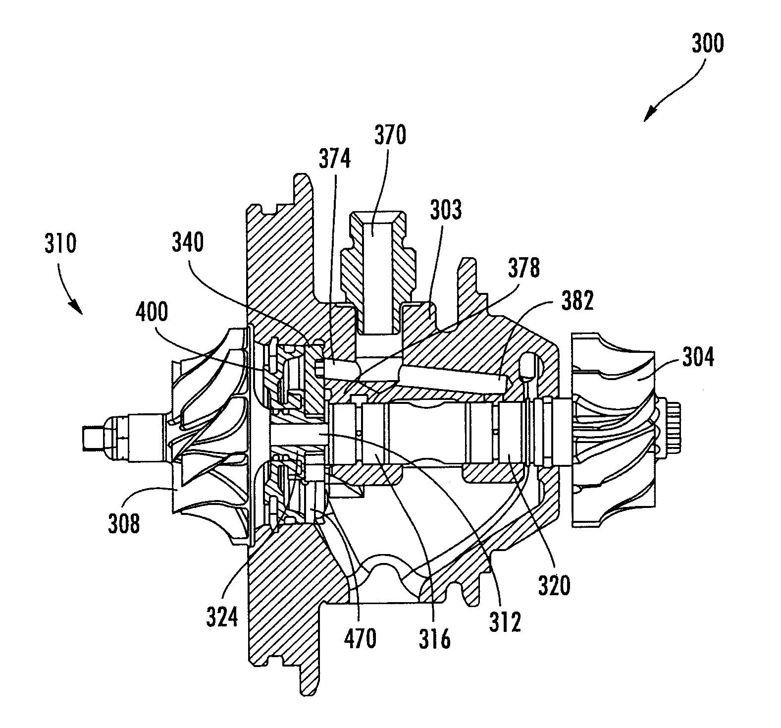
[0036]Exemplary embodiments described herein are directed to an oil discharge assembly for a turbocharger. Aspects will be explained in connection with several possible embodiments of oil discharge assemblies, but the detailed description is intended only as exemplary. The particular type of turbocharger that utilizes the exemplary embodiments of the oil discharge assemblies described herein can very including, but not limited to, two stage turbocharger configurations and / or low pressure stage turbochargers, single stage turbochargers, variable geometry turbochargers and other types of turbochargers. The exemplary embodiments are shown with cast rear walls. However, the present disclosure contemplates use of the oil discharge assemblies with or without cast rear walls, for example, with bolted rear walls and / or using an oil deflection plate rather than a bearing housing lid. Exemplary embodiments are shown in FIGS. 6-13, but the present disclosure is not limited to the illustrated s...


PUM

PropertyMeasurementUnit
Flow rateaaaaaaaaaa
Shapeaaaaaaaaaa

Abstract

A turbocharger oil discharge assembly (301, 501, 701, 901) can have a thrust collar (324, 524, 724, 924) with a first radially outwardly extending wall and a second radially outwardly extending wall to define a first annular channel. The first radially outwardly extending wall can have an annular flange that at least in part defines a second annular channel. The assembly can also have a thrust bearing (340, 540, 740, 940) having a radially inner end received in the first annular channel, and an insert (400, 600, 800, 1000). An oil collection chamber (440, 640, 840, 1040) can be defined at least in part by a drainage channel of the insert (400, 600, 800, 1000), the annular flange of the thrust collar (324, 524, 724, 924) and the thrust bearing (340, 540, 740, 940). Pressurized oil discharged from an oil release interface can be directed towards a radially outer region of the oil collection chamber (440, 640, 840, 1040) and can be collected in the oil collection chamber (440, 640, 840, 1040) for subsequent exhaust.

Description

FIELD OF THE INVENTION[0001]The invention relates in general to turbochargers and, more particularly, to oil leakage prevention in a turbocharger.BACKGROUND OF THE INVENTION[0002]Turbochargers can have a turbine wheel that is connected by a shaft to a compressor wheel. The turbine wheel is driven by exhaust gas exiting an internal combustion engine. The rotation of the turbine wheel is communicated to the compressor wheel by the shaft. The compressor wheel is used to increase the pressure of intake air prior to mixing with fuel and combustion in the engine. The speeds at which the shaft, turbine wheel and compressor wheel are rotated is very high, and can be in excess of 60,000 rpm including up to or above 300,000 rpm. Bearings used to support the shaft therefore must be lubricated with pressurized oil. During normal operation of the turbocharger, pressure within the compressor is sufficient to retard the flow of oil from the area of the bearings into the compressor. During certain ...

Claims


Application Information

Patent Timeline
IPC IPC(8): F02B39/14B23P11/00F16C33/10F16C33/74
CPCF01D25/16F01D25/18F01D25/183Y10T29/4932F02C6/12F05D2220/40F05D2240/55F02B39/14
Inventor KOCH, SILVIOPANEK, EDWARD R.TAKABATAKE, LAURO
Owner BORGWARNER INC
Why Eureka
Try Eureka