Decoupled pressurised retort

a technology of retort and retort, which is applied in the field of pressurized retort, can solve the problems of long heating time, increased cost and low throughput, and product can be overcooked in the interior of the tin or burnt onto the wall of the tin, so as to achieve cost savings, increase throughput, and increase production facilities

Inactive Publication Date: 2010-06-10
MARS INC
View PDF8 Cites 4 Cited by
  • Summary
  • Abstract
  • Description
  • Claims
  • Application Information

AI Technical Summary

Benefits of technology

[0021]It has surprisingly been found that by providing compensators on the retort, preferably on the retort wall, preferably in targeted positions, substantially complete decoupling between the drive and the pressurized vessel is possible, the seals are decoupled and are connected to the drive system, and all forces and vibrations can be dissipated directly into the foundation or the floor outside the pressurized vessel. With the pressurized retort of the invention, it is not necessary to change the pressurized vessel per se; on the contrary, standard retorts can be used and adapted accordingly. In accordance with the invention, it is possible to keep the container free from the high alternating loads that occur, since it is possible in particular to separate the forces acting on the retort container and drive, i.e. parts bearing forces are decoupled from the retort container, so that no flow of forces can occur. The overall consequence of this is that the pressurized retort can be operated substantially free of vibrations. In addition, it becomes apparent that the positioning of the drive, either outside or inside the retort container, is not of decisive importance for the pressurized retort of the invention. With the pressurized retort of the invention, it is likewise possible to design it with such a size that it is possible to sterilize and thus introduce a plurality of containers, even fairly large ones, into the retort simultaneously. With the pressurized retort of the invention, larger production facilities can therefore be designed, which lead to cost savings because of the higher throughput.

Problems solved by technology

This leads to a long heating-up time, entailing increased costs and a low throughput.
As a consequence of being exposed to heat for such a long time, however, the product can be overcooked in the interior of the tin or can burn onto the wall of the tin.
A pressurized retort involved in thermal treatment is a very complex system with a large number of very sensitive sensors, such as calibrated instruments for measuring the temperature and pressure, means for monitoring the filling levels, and control valves, which can easily be damaged.
The retorts known from the state of the art, in which containers are moved, still have disadvantages with regard to the conditions described above.
In addition, all that is known from the state of the art so far is that only a single container is placed in a retort, which has made it impossible to construct larger production facilities.

Method used


Image

  • Decoupled pressurised retort
  • Decoupled pressurised retort

Examples


Embodiment Construction

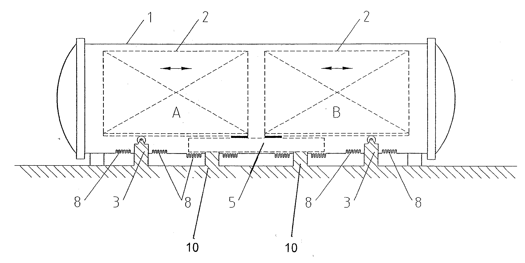
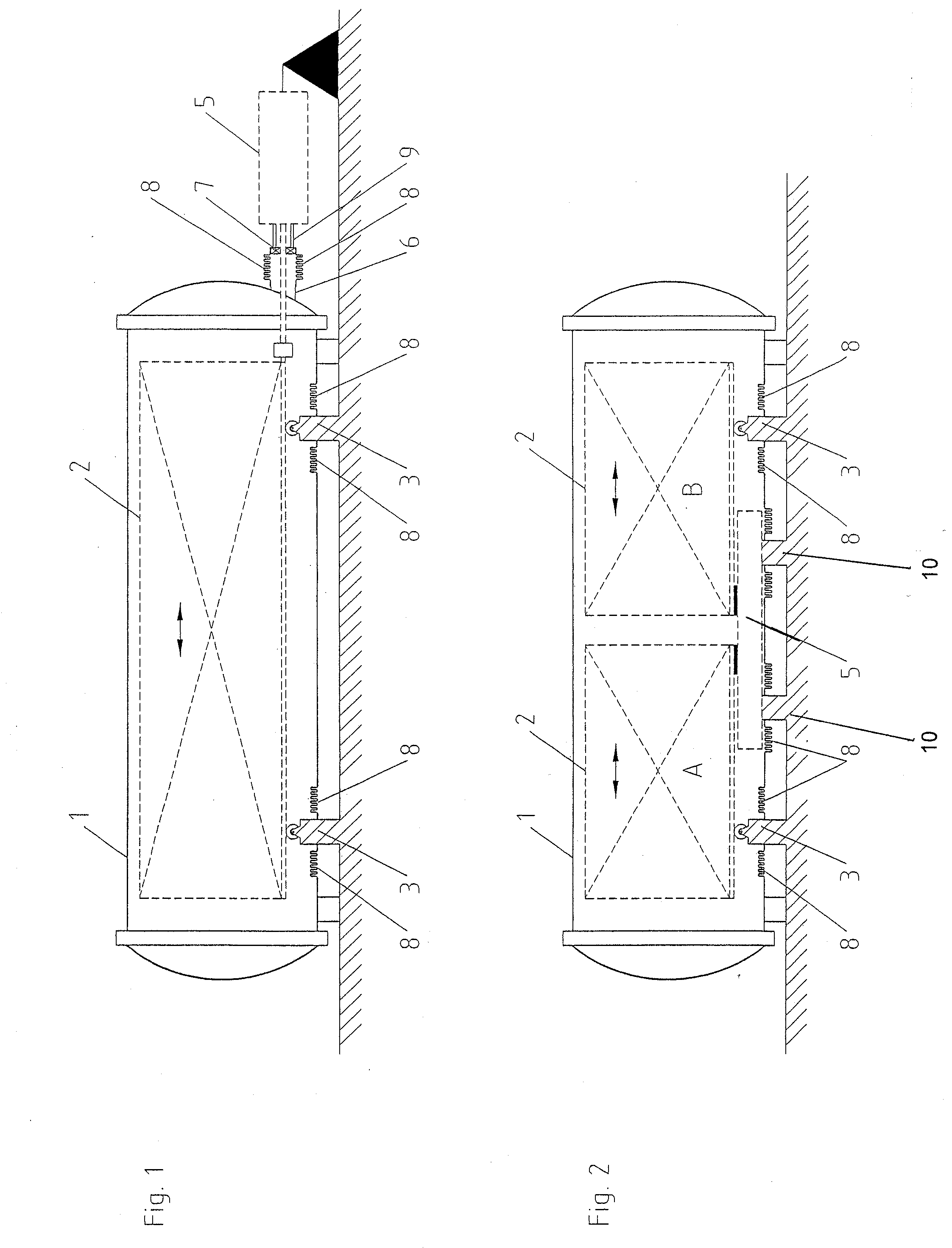
[0025]FIG. 1 shows a pressurized retort 1 in cross-section. Inside the retort 1 there is disposed a container 2, in which tins, for example, may be placed, in order to sterilize their contents. The container 2 is supported on two bearings 3, which connect to the floor. The container 2 is also connected via a drive rod 4 with a drive 5, which drive 5 likewise connects to the floor. Between the pressurized retort 1 or a pipe coupling 6 thereof, the drive rod 4 and the drive 5, a seal 7 is provided at the entry point of the drive rod 4 into the retort 1, which ensures a substantially complete seal of the interior of the retort 1. Forces are dissipated here via tie rods 9. Adjacent to the seal 7, compensators 8 are provided at the pipe coupling 6, such as in the form of springs or thin sheets of metal. Compensators 8 can likewise be found on the retort walls adjacent to the bearing 3.

[0026]During operation of the pressurized retort of the invention 1, the container 2 disposed in the ret...


PUM


Abstract

The present invention relates to a pressurized retort with at least one container disposed therein. The container is movable in the retort via a drive and the container is supported by at least one bearing in the retort, wherein one or more compensator(s) is/are attached to the retort to provide a decoupling between the interior of the retort, the retort itself and the exterior of the retort.

Description

CROSS-REFERENCE TO RELATED APPLICATIONS[0001]This Application is a National stage of International Application PCT / EP2007 / 011054 filed on Dec. 17, 2007 which claims priority to Application 10 2006 062 086.0-41 filed on Dec. 29, 2006 in Germany.TECHNICAL FIELD[0002]The present invention relates to a pressurized retort with at least one container disposed therein, the container being movable in the retort via a drive and the container being supported by at least one bearing in the retort.BACKGROUND OF THE INVENTION[0003]Pressurized retorts are used, for example, in the sterilization of foodstuffs which are to be packed in tins. Foodstuffs packed in tins require different processing times for sterilization, depending on their viscosity.[0004]Whereas comparatively low-viscosity products allow convective heat to be introduced into the product very quickly by thermal conductivity, it takes considerably longer in the case of more viscous products until the temperature of preferably 115-130...

Claims


Application Information

Patent Timeline
Patent Type & Authority Applications(United States)
IPC IPC(8): A23L3/10A23L3/14
CPCA23L3/14B65B65/02B65B65/00B65B55/02
Inventor CORDES, HERBERTKREGEL, GEBHARD
Owner MARS INC
Why Eureka
Try Eureka