Solar Energy Collection System

a solar energy and collection system technology, applied in the field of solar energy collection system, can solve the problems of large environmental problems, high construction costs, and the pace of today's fast-increasing speed, and achieve the effect of less expensive manufacture and implementation

Active Publication Date: 2010-06-10
ASHKIN ARTHUR
View PDF31 Cites 15 Cited by
  • Summary
  • Abstract
  • Description
  • Claims
  • Application Information

AI Technical Summary

Benefits of technology

[0016]It is another advantage of the present invention that the tapered pyramidal geometry of planar, mirrored sidewalls is significantly less expensive to manufacture and implement than the prior art “spiral horn” arrangement described above. Indeed, the square-based truncated pyramidal solar collector embodiment of the present invention can be formed as a ziggurat-like structure that is lightweight and inexpensive. The circular conic embodiment of the present invention is readily fabricated for relatively small dimensions (such as may be utilized in residential applications), but may be more difficult in larger sizes—where any of the multi-sided truncated pyramidal arrangements (triangular, square, rectangular, pentagonal, or the like) may be more appropriate.

Problems solved by technology

Such usage has caused vast environmental problems, starting from as early as the Industrial Revolution and continuing today at an almost unabated pace.
High construction costs and the difficulty of achieving high solar cell efficiencies are the principal factors in preventing the extensive use of most presently-available systems.
The present cost of production of the best solar PV cells is approximately $3-$6 per watt, which is prohibitive when compared with a current cost of about $0.50 per watt for fossil fuels.
All thin-film approaches thus far have lowered the cost of the PV material, but at the expense of module efficiency.
Traditionally, design approaches for concentrating collectors have been large and bulky, using Fresnel lenses or large area parabolic reflectors.
These arrangements have large single-element focusing optics, requiring highly accurate and expensive feedback-controlled solar tracking mechanisms.
The efficiency of this arrangement, however, remains limited in terms of the angle of acceptance of the incoming radiation and the need to accurately track the movement of the sun to provide a practical arrangement.
While potentially interesting from a design point of view, the formation of such a spiral horn had extensive manufacturing difficulties which may result in a cost-prohibitive option.
The state of the art approaches have not adequately addressed the issues of optical efficiency, optical cost, heat dissipation, solar tracking tolerance and size and weight concerns.
Although interest in solar energy usage is high, experts predict it will take years (varying from a few years to a few decades) and large investments of capital and possibly government subsidies to significantly reduce our dependence on fossil fuels.

Method used


Image

  • Solar Energy Collection System
  • Solar Energy Collection System
  • Solar Energy Collection System

Examples


Embodiment Construction

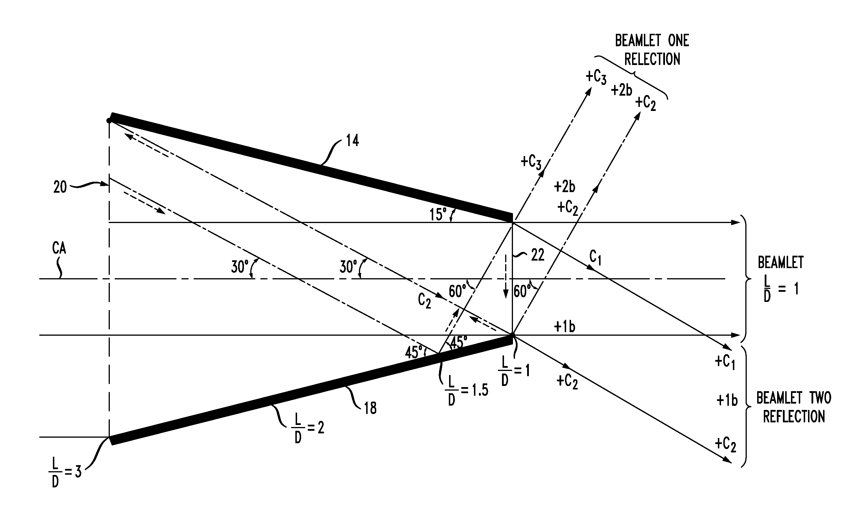
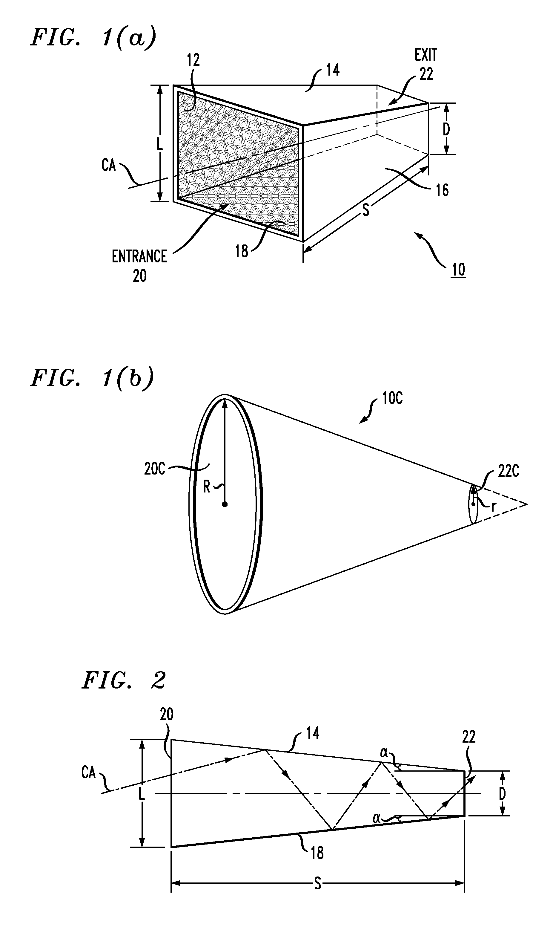
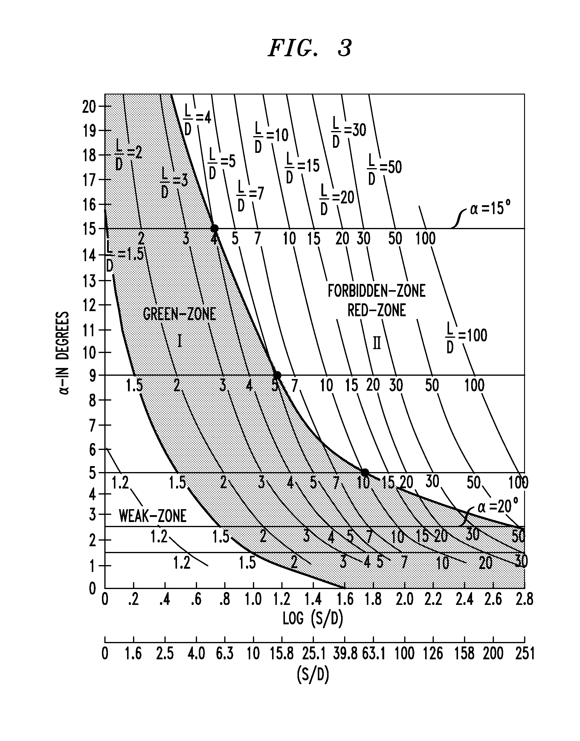
[0035]A novel way of concentrating radiant energy using multiple reflections of light passing down a tapered pyramidal-type structure made from highly-reflective mirrored surfaces is the subject of the present invention. It has been discovered that tapered structures such as these have many properties that make them not only useful, but superior to existing solar collectors. FIG. 1(a) illustrates an exemplary embodiment of a right-angled truncated pyramidal solar collector 10 formed in accordance with the present invention. In this case, collector 10 utilizes a square geometry entrance port and exit port, with tapered reflective sidewalls disposed therebetween. That is, collector 10 is formed of a set of four tapered, planar reflective sidewalls 12, 14, 16 and 18. Collector 10 is shown as having an entrance 20 of dimension L (and area, therefore, of L2). Collector 10 has a length S, tapering downward to an exit 22 of dimension D (and area of D2). Although not explicitly shown, it is...


PUM


Abstract

A solar collector utilizes multiple reflections of light passing down a tapered, pyramidal-type structure made of highly-reflective mirrored surfaces. A right-angled truncated reflective pyramidal structures have been discovered to have many properties which make them superior to existing concentrator geometries. The use of a tapered, pyramidal-type structure creates multiple reflections which appear at the collector output in the form of a Buckminster-Fullerene display, providing improved collector efficiency and amplification when compared to prior art “concentrators” of the Fresnel lens or parabola type.

Description

CROSS-REFERENCE TO RELATED APPLICATIONS [0001]This application claims the benefit of U.S. Provisional Application No. 61 / 176,748, filed May 8, 2009 and herein incorporated by reference.TECHNICAL FIELD [0002]The present invention relates to a solar energy collection system and, more particularly, to a solar collector of a preferred tapered geometry that allows for significantly improved concentration efficiency, while also relaxing the requirements on tracking the movements of the sun; the inventive system also provides a means of reducing energy generation costs well below those associated with standard fossil fuels.BACKGROUND OF THE INVENTION[0003]Most present day energy usage is derived from the sun. This comes largely from the burning of fossil fuels. Such usage has caused vast environmental problems, starting from as early as the Industrial Revolution and continuing today at an almost unabated pace. Indeed, the subsequent neglect of these growing problems has given rise to the p...

Claims


Application Information

Patent Timeline
Patent Type & Authority Applications(United States)
IPC IPC(8): H01L31/058G02B5/09H01L31/052
CPCG02B17/004Y02E10/52H01L31/0547G02B19/0042G02B19/008G02B19/0019
Inventor ASHKIN, ARTHUR
Owner ASHKIN ARTHUR
Why Eureka
Try Eureka