Flow rate range variable type flow rate control apparatus

a flow rate control and variable-type technology, applied in water supply installation, process and machine control, instruments, etc., can solve the problems of difficult to reduce installation costs, difficult to compensate for the degradation of control accuracy in a low flow rate state, and unavoidable increase in installation costs, so as to achieve high-quality flow rate control and simple operation of flow rate control

Active Publication Date: 2010-06-10
FUJIKIN INC +2
View PDF11 Cites 39 Cited by
  • Summary
  • Abstract
  • Description
  • Claims
  • Application Information

AI Technical Summary

Benefits of technology

[0027]The present invention is constituted so that flow rate is controlled in a manner wherein flow rate control is performed by appropriately combining an orifice 8c for a large flow quantity, an orifice 8a for a small flow quantity (or an orifice 8c for a large flow quantity, an orifice 8b for a medium flow quantity and an orifice 8a for a small flow quantity), thus making it possible that highly accurate flow rate control may be achieved over a wide flow rate range with an error of less than 1% of the set point. Also, the present invention makes operation of flow rate control simple because a flow rate control range can be automatically selected by operating a switching valve. Furthermore, the present invention can be applied to flow rate control of various kinds of fluid supply facilities because of ease of change of the type of gases supplied by making use of a flow factor F.F. in the case wherein flow rate control of fluid is basically under a critical condition.

Problems solved by technology

Thus, it is difficult to make up for the degradation of control accuracy in a low flow rate state using only a flow rate control apparatus provided with a feature with which to correct a measured value.
However, in a system, in which a plurality of devices responsible for different flow rate control ranges, respectively, are provided in parallel, installation costs unavoidably go up, which makes it difficult to reduce the installation costs.
At the same time, switching operations of flow rate control apparatuses become time-consuming and troublesome.

Method used


Image

  • Flow rate range variable type flow rate control apparatus
  • Flow rate range variable type flow rate control apparatus
  • Flow rate range variable type flow rate control apparatus

Examples


embodiment 1

[0061]Referring to the drawings, embodiments of the present invention are described as follows.

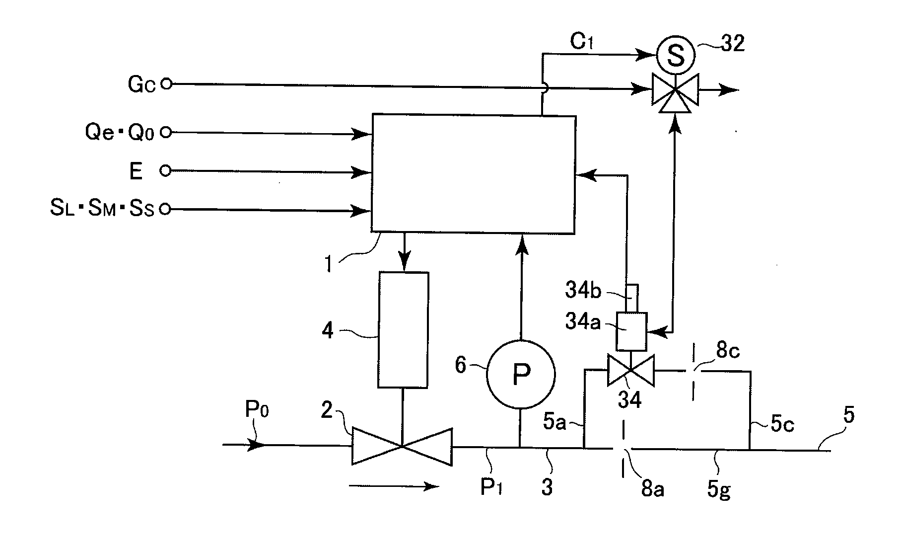
[0062]FIG. 1 is a block diagram of a flow rate range variable type flow rate control apparatus according to one embodiment of the present invention. In FIG. 1, 1 designates a control part, 2 designates a control valve, 3 designates an orifice upstream side (primary side) pipe, 4 designates a valve driving part, 5 designates a fluid supply pipe, 6 designates a pressure sensor, 8a designates an orifice for a small flow quantity, 8b designates an orifice for a medium flow quantity, 8c designates an orifice for a large flow quantity, 32, 33 designate switching electro-magnetic valves, and 34, 35 designate switching valves. The control part 1, the control valve 2, the valve driving part 4, the pressure sensor 6, and the like, of the afore-mentioned pressure type flow rate control apparatus have been disclosed. With respect to the control part, there are provided flow rate input / output signals (...

embodiment 2

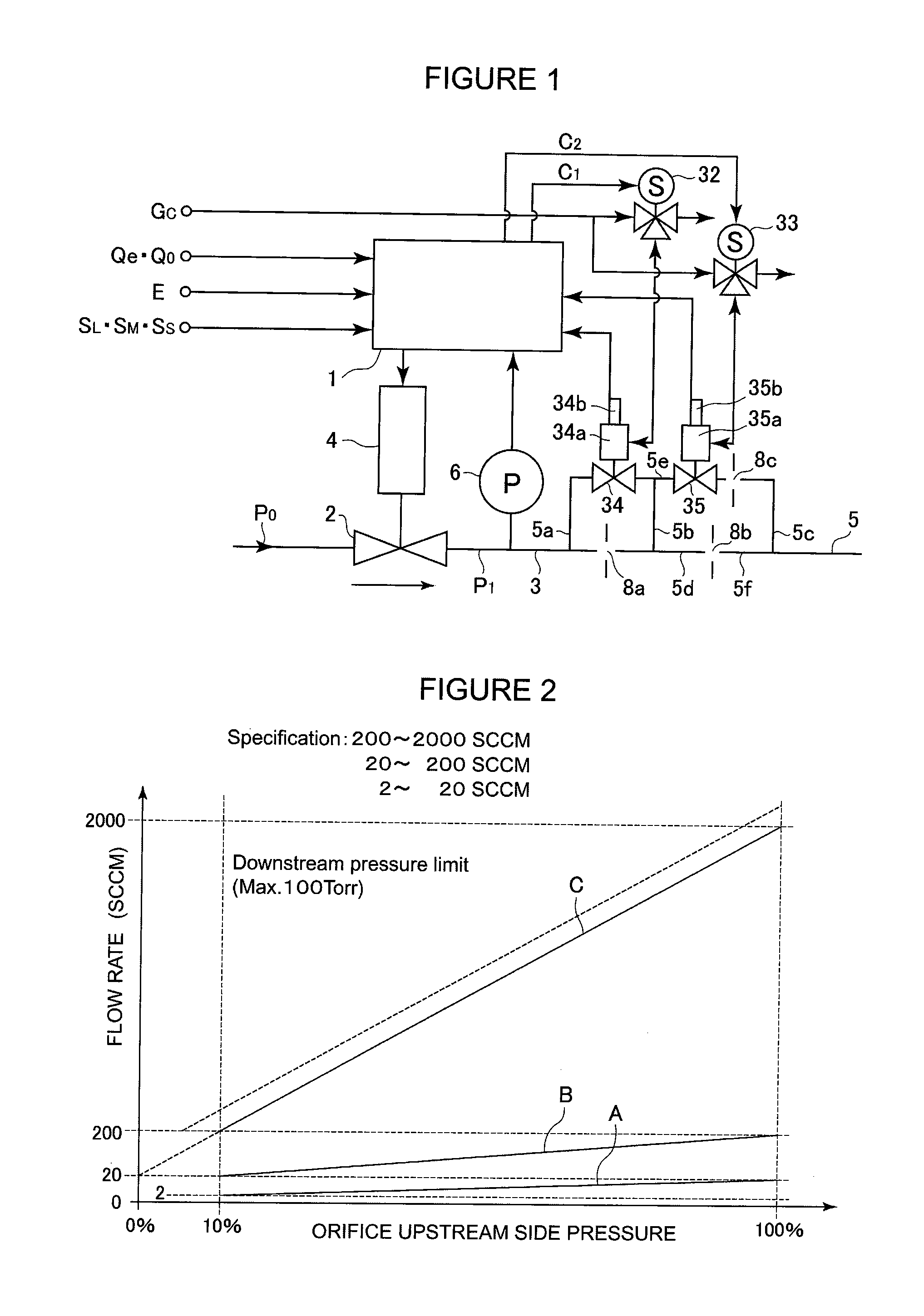
[0067]FIG. 3 shows another embodiment of the present invention, wherein flow rate control is appropriately performed by employing an orifice 8a for small flow quantity and an orifice 8c for large flow quantity. For example, in the case that flow rate control for a maximum flow rate of 2000 SCCM is performed, the apparatus is constructed so that a flow rate up to 200 SCCM is controlled by the orifice 8a for small flow quantity and a flow rate up to 2000 SCCM is controlled by the orifice 8c for large flow quantity. Specifically, in the case that a flow rate of up to 200 SCCM is controlled, the switching valve 34 is maintained in a state of closing (i.e., closed), and the flow rate QS of a fluid passing through the orifice 8a for small flow quantity is controlled as QS=KSP1 (where Ks is a constant specific to the orifice 8a). By using the orifice 8a for small flow quantity, the flow rate can be controlled accurately with an error of less than ±1% set point over the flow rate range of 2...

embodiment 3

[0072]FIG. 6 shows yet another embodiment of the present invention wherein a so-called thermal type mass flow rate control apparatus MFC is employed in a flow rate control apparatus. As shown in FIG. 6, the thermal type mass flow rate control apparatus comprises a control part 36, a flow rate control valve 37, a laminar flow element bypass part 38, a flow rate sensor part 39, a switching valve 41, 42, and the like. Temperature changes in proportion to a mass flow rate of a fluid are detected with a flow rate sensor part 39, and fluid of a certain set flow rate is made to flow out by controlling the flow rate control valve 37 for opening and closing based on the detected temperature. A thermal type mass flow rate control apparatus MFC itself has been disclosed. Therefore, a detail description of such is omitted here.

[0073]In FIG. 6, 36a designates a bridge circuit, 36b designates an amplification circuit, 36c designates a correction circuit, 36d designates a comparison circuit, 36e d...


PUM


Abstract

A pressure type flow control device enabling a reduction in size and an installation cost by accurately controlling the flow of a fluid in a wide flow range. Specifically, the flow of the fluid flowing in an orifice (8) is calculated as Qc=KP1 (K is a proportionality factor) or Qc=KP2m(P1−P2)n (K is a proportionality factor and m and n are constants) by using a pressure P1 on the upstream side of the orifice and a pressure P2 on the downstream side of the orifice. A fluid passage between the downstream side of the control valve of the flow control device and a fluid feed pipe is formed of at least two or more fluid passages positioned parallel with each other. Orifices with different fluid flow characteristics are interposed in the fluid passages positioned parallel with each other. For the control of the fluid in a small flow area, the fluid in the small flow area is allowed to flow to one orifice. For the control of the flow in the large flow area, the fluid in the large flow area is allowed to flow to the other orifice by switching the fluid passages.

Description

[0001]This is a National Phase Application in the United States of International Patent Application No. PCT / JP2006 / 312952 filed Jun. 22, 2006, which claims priority on Japanese Patent Application No. 2005-185845, filed Jun. 27, 2005. The entire disclosures of the above patent applications are hereby incorporated by reference.FIELD OF THE INVENTION[0002]The present invention relates to a flow rate control apparatus with a fluid supply system used for semiconductor manufacturing facilities, chemical products manufacturing facilities, pharmaceutical products manufacturing facilities, food products manufacturing facilities, and the like. More particularly, the present invention relates to a flow rate range variable type flow rate control apparatus with which both the expansion of a flow rate control range and the maintenance of high control accuracy can be easily achieved with a pressure type flow rate control apparatus and a thermal type mass flow rate control apparatus.BACKGROUND OF T...

Claims


Application Information

Patent Timeline
Patent Type & Authority Applications(United States)
IPC IPC(8): F15D1/00
CPCG05D7/0635G01F1/363G01F1/6842G01F1/6847G01F5/005G01F7/005G05D7/0647Y10T137/0379Y10T137/7759Y10T137/776Y10T137/8593Y10T137/86734Y10T137/86815Y10T137/87265Y10T137/87314Y10T137/8741Y10T137/87499Y10T137/87684G05D7/00G05D7/0641G05D23/1927
Inventor OHMI, TADAHIROSAITO, MASAHITOHINO, SHOICHISHIMAZU, TSUYOSHIMIURA, KAZUYUKINISHINO, KOUJINAGASE, MASAAKISUGITA, KATSUYUKIHIRATA, KAORUDOHI, RYOUSUKEHIROSE, TAKASHISHINOHARA, TSUTOMUIKEDA, NOBUKAZUIMAI, TOMOKAZUYOSHIDA, TOSHIHIDETANAKA, HISASHI
Owner FUJIKIN INC
Why Eureka
Try Eureka