Multi-step pressurized switch

Inactive Publication Date: 2010-06-10
HANBIT TECH & INNOVATION
View PDF4 Cites 9 Cited by
  • Summary
  • Abstract
  • Description
  • Claims
  • Application Information

AI Technical Summary

Benefits of technology

[0011]The exemplary embodiments are directed to a multi-step pressurized switch fabricated with a simpler PCB structure in a lower product cost.
[0012]The exemplary embodiments are

Problems solved by technology

However, such pressurized switches are usually formed by fixing the elastic plates to printed circuit boards (PCB) in a form of reclamation, so it makes their fabrication processes complicated.
Further, as signals from the pressurized switch are v

Method used


Image

  • Multi-step pressurized switch
  • Multi-step pressurized switch
  • Multi-step pressurized switch

Examples


Embodiment Construction

[0036]Hereinafter, preferred embodiments of the present invention will be described with reference to the accompanying drawings. The matters defined in the description, such as the detailed construction and elements, are nothing but specific details provided to assist those of ordinary skill in the art in a comprehensive understanding of the invention, and thus the present invention is not limited thereto. The same drawing reference numerals are used for the same elements across various figures.

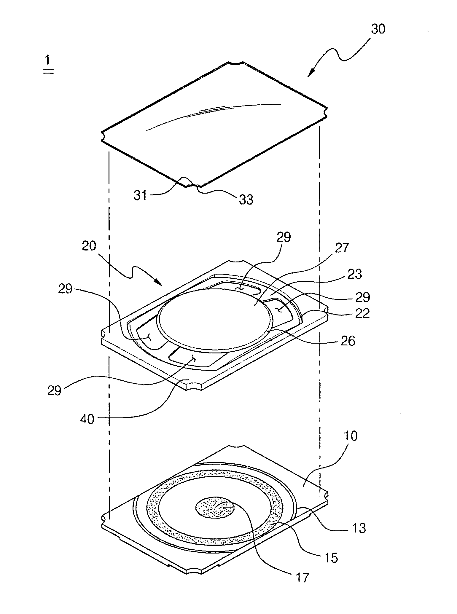
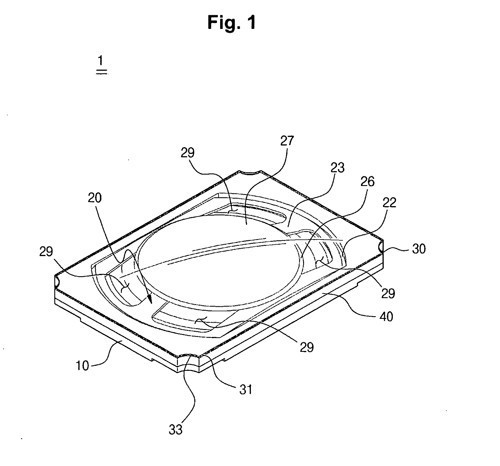
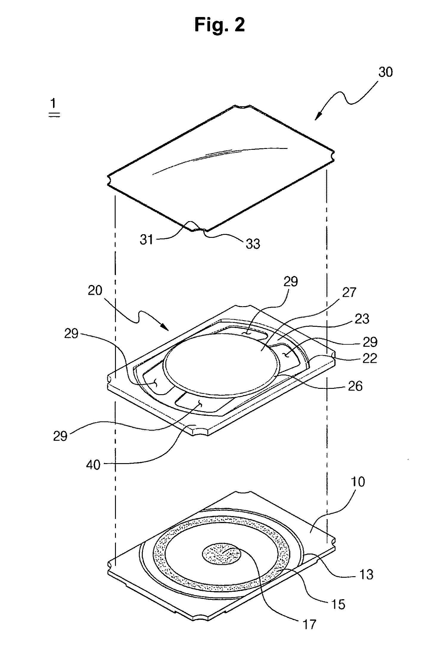
[0037]FIG. 1 perspectively shows a multi-step pressurized switch according to a preferred embodiment of the present invention and FIG. 2 divisionally shows the multi-step pressurized switch shown in FIG. 1. And, FIGS. 3A through 3C show an operational feature of the multi-step pressurized switch shown in FIG. 1.

[0038]Referring to FIGS. 1 through 3C, the multi-step pressurized switch 1 may be comprised of an elastic plate 20, a switched printed circuit board (hereinafter, referred to as “switc...


PUM


Abstract

Disclosed is a multi-step pressurized switch providing various signals in response to variation of pressure applied thereto. The multi-step pressurized switch includes a switched PCB connected to a PCB of an electronic device and having at least one or more contact points on the top, and an elastic plate settled on the top of the switched PCB and electrically connecting the contact points with each other if there is pressure. The elastic plate includes a first projection protruding upward from the edge of the elastic plate, a second projection joining with the first projection and protruding in the same direction with the first projection, and a first slope bending down toward a direction opposite to the first projection from the edge of the elastic plate.

Description

CROSS-REFERENCE TO RELATED APPLICATION[0001]This application is based on and claims priority from Korean Patent Application Nos. 10-2008-0124217, 10-2009-0001478, 10-2009-0002993 and 10-2009-0082826 filed on Dec. 8, 2008, Jan. 8, 2009, Jan. 14, 2009 and Sep. 3, 2009, respectively in the Korean Intellectual Property Office, the disclosure of which is incorporated herein in its entirety by reference.BACKGROUND OF THE INVENTION[0002]1. Field of the Invention[0003]Exemplary embodiments relate generally to pressurized switches capable of providing different signals variable by pressure applied thereto.[0004]2. Description of the Prior Art[0005]A pressurized switch, having a conductor that operates by moving up and down between contact points separated from each other, is generally used for controlling an on / off operation of a system since it generates just a single signal by contacting the conductor between the contact points.[0006]In recent years, with the trends toward the scaling-down...

Claims


Application Information

Patent Timeline
IPC IPC(8): H01H1/10
CPCH01H13/48H01H2205/018H01H2205/026H01H2215/016H01H2215/024H01H2225/018H01H2239/004H01H13/44H01H13/64H01H2215/022
Inventor LEE, GEUN JU
Owner HANBIT TECH & INNOVATION
Why Eureka
Try Eureka