Excited gas injection for ion implant control

a technology of excited gas and ion implants, which is applied in the direction of ion beam tubes, energy-based chemical/physical/physico-chemical processes, coatings, etc., can solve the problem of not fully exploiting the control of the characteristics of the incoming sour

Active Publication Date: 2010-06-10
VARIAN SEMICON EQUIP ASSOC INC
View PDF9 Cites 18 Cited by
  • Summary
  • Abstract
  • Description
  • Claims
  • Application Information

AI Technical Summary

Benefits of technology

The present technology provides an improved ion source with enhanced performance capabilities. It uses modified and/or atomic gas injection techniques to generate various types of ions and other particles needed for industrial processes such as semiconductor manufacturing. By introducing plasma generated from a separate device into the processing chamber, this approach allows for better control over the desired chemical composition of the resulting products. Additionally, combining different gases in a controlled manner leads to increased efficiency and flexibility during operation. Overall, these technical improvements enhance the precision and effectiveness of plasma-based tools used in industry today.

Problems solved by technology

This patent describes two methods for generating plasma in a plasma doping system: plasma immersion and plasma immersion plus a shield ring. Both methods involve supplying a primary dopant gas to the process chamber and measuring its concentration therein. The problem addressed by this patent is how to control the compositions of the ions generated during the plasma formation process by adjusting the properties of the source gas.

Method used


Image

  • Excited gas injection for ion implant control
  • Excited gas injection for ion implant control
  • Excited gas injection for ion implant control

Examples


Embodiment Construction

[0038]FIG. 5 illustrates a first embodiment of a gas injection system used in an ion beam application. Traditionally, gas source 40 is in direct fluid communication with source chamber 14. However, FIG. 5 illustrates the components of the gas injection system according to a first embodiment. In this embodiment, gas source 40 may be in communication with a mass flow controller (MFC) 220. The MFC is responsible for regulating the flow of gas from gas source 40 to a desired flow rate. The output of the MFC is in fluid communication with adjustable bypass valve 210 and remote plasma source 200. The outputs from the adjustable bypass valve 210 and the remote plasma source 200 then join together and are in fluid communication with the source chamber 14.

[0039]The remote plasma source 200 can be of any suitable type. However, those sources having a wide operating range with high-density plasma and / or excited neutral species generation capability are preferred. In one embodiment, a microwave...


PUM

PropertyMeasurementUnit
Pressureaaaaaaaaaa
Poweraaaaaaaaaa
Flow rateaaaaaaaaaa

Abstract

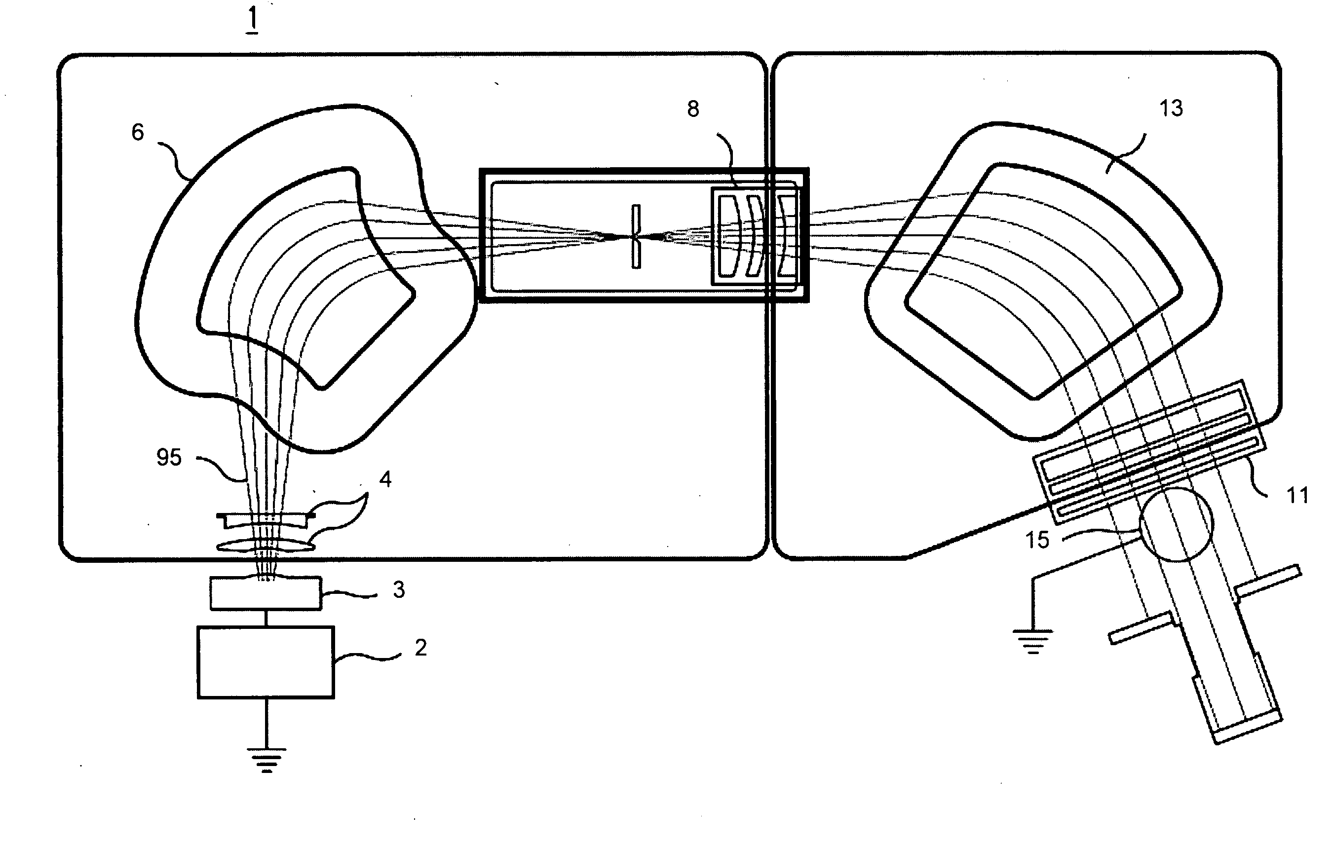
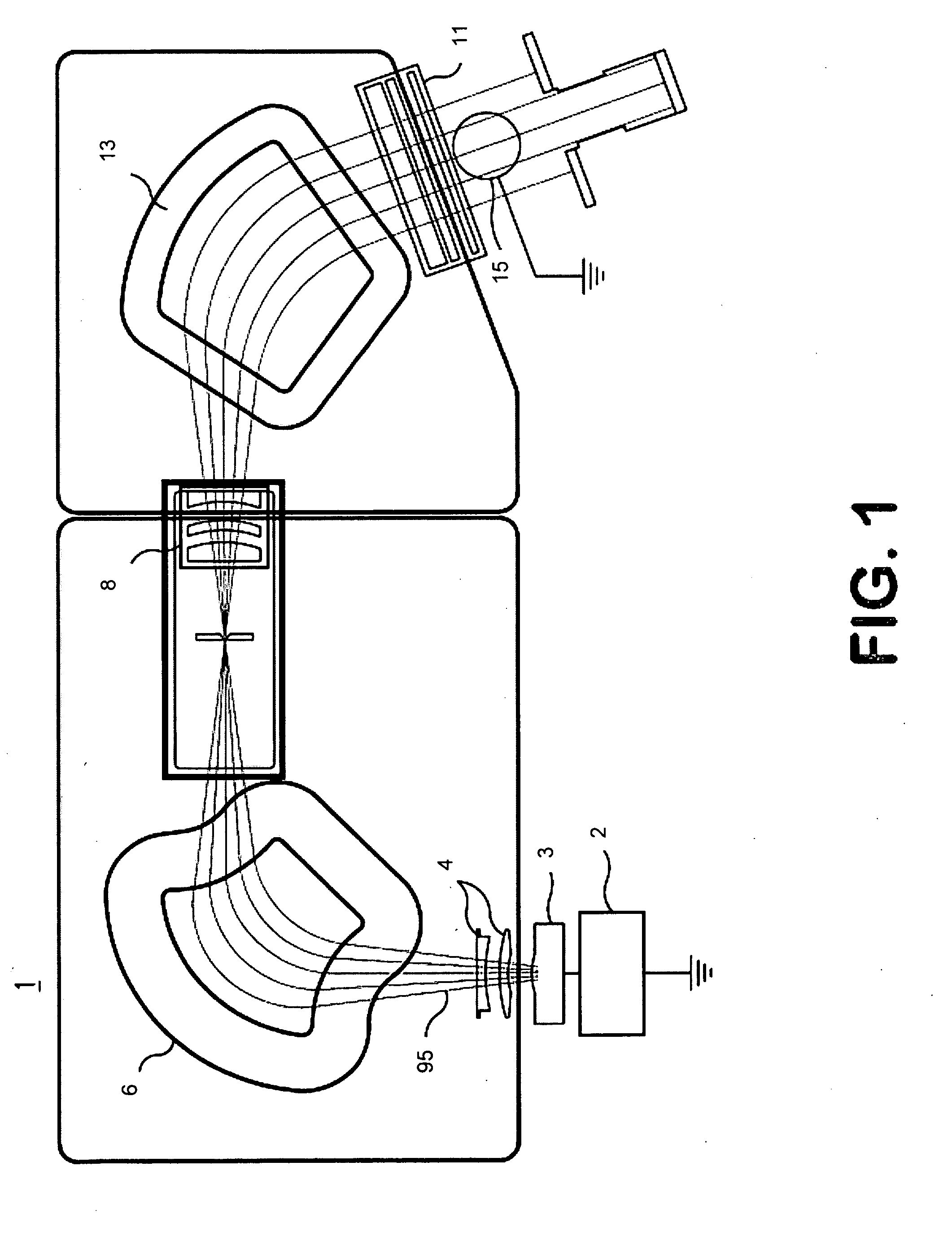
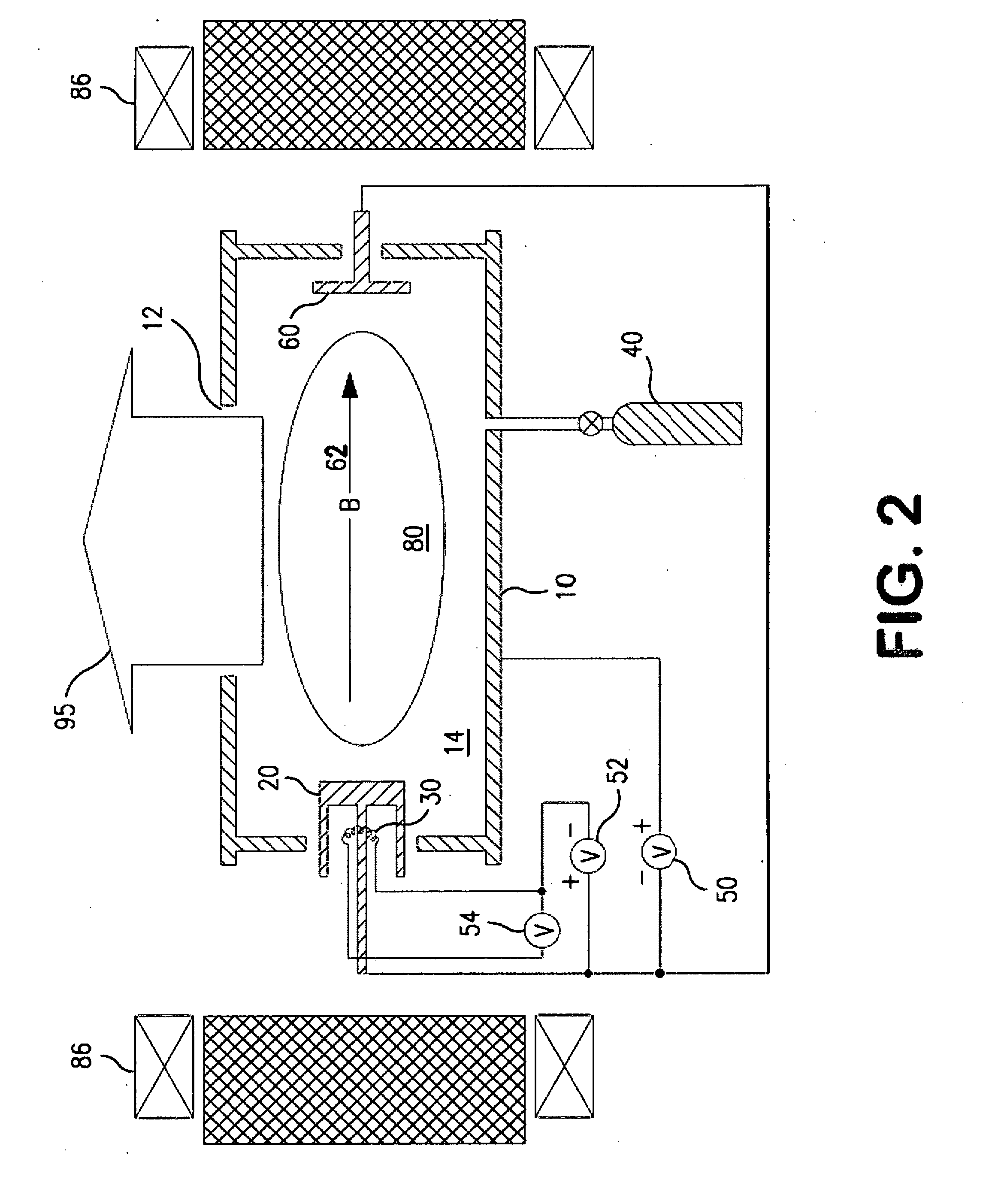
An ion source that utilizes exited and/or atomic gas injection is disclosed. In an ion beam application, the source gas can be used directly, as it is traditionally supplied. Alternatively or additionally, the source gas can be altered by passing it through a remote plasma source prior to being introduced to the ion source chamber. This can be used to create excited neutrals, heavy ions, metastable molecules or multiply charged ions. In another embodiment, multiple gasses are used, where one or more of the gasses are passed through a remote plasma generator. In certain embodiments, the gasses are combined in a single plasma generator before being supplied to the ion source chamber. In plasma immersion applications, plasma is injected into the process chamber through one or more additional gas injection locations. These injection locations allow the influx of additional plasma, produced by remote plasma sources external to the process chamber.

Description


Claims


Application Information

Patent Timeline
Owner VARIAN SEMICON EQUIP ASSOC INC
Why Eureka
Try Eureka