Pivotally deployable air dam utilizing active material actuation

a technology of active material and air dam, which is applied in the direction of roofs, mechanical equipment, transportation and packaging, etc., can solve the problems of reducing the effectiveness of the air dam, reducing the useful life, and increasing so as to reduce the damage to the air dam, reduce the cost of associative repair and/or replacement, and simplify the effect of non-binding motion

Inactive Publication Date: 2010-06-10
DYNALLOY +1
View PDF8 Cites 67 Cited by
  • Summary
  • Abstract
  • Description
  • Claims
  • Application Information

AI Technical Summary

Benefits of technology

[0006]Utility of invention includes the ability to reversibly stow the dam through remote actuation either on-demand or through control algorithms based on sensor input which reduces the likelihood of damaging the air dam in comparison to fixed models, and therefore expands upon the available applications of dams.
[0007]The pivotal construction of the dam results in more efficient means of sealing the actuator from external environments and foreign objects, such as road debris, snow and ice. Moreover, means of effecting non-binding motion is also simplified in comparison to linearly deployed dams. Additionally the pivot const

Problems solved by technology

Due to their proximity to the ground, however, conventional dams present various concerns in the art, such as for example, a propensity to become damaged (e.g., by scraping or coming in contact with foreign objects/the ground).
Sporadic impact often permanently alters the shape of the dam thereby reducing its effectiveness.
Th

Method used


Image

  • Pivotally deployable air dam utilizing active material actuation
  • Pivotally deployable air dam utilizing active material actuation
  • Pivotally deployable air dam utilizing active material actuation

Examples


Embodiment Construction

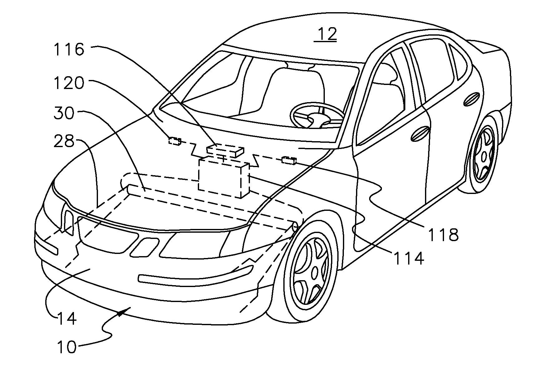
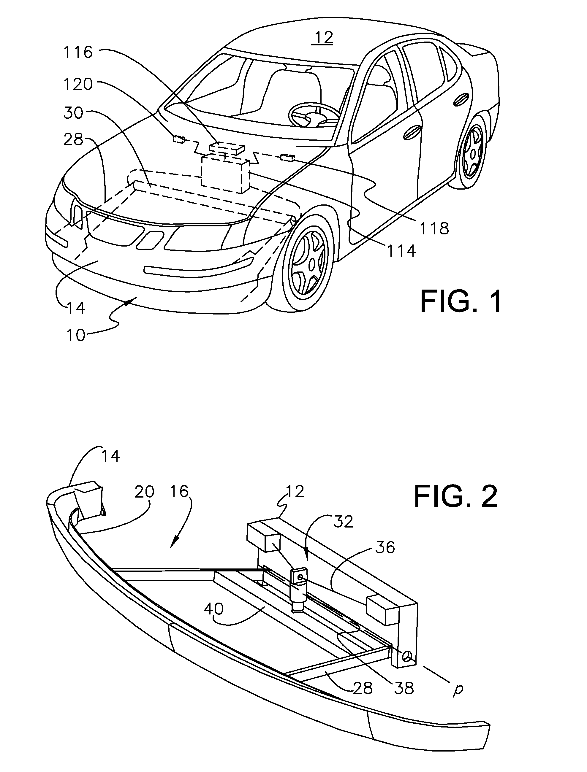
[0027]As shown in FIGS. 1-10a, the present invention concerns pivotally deployable air dams 10 having active material actuation. In the illustrated embodiments, the air dam 10 is exemplarily employed by and utilized with respect to a vehicle 12, such as an automobile, truck, or SUV. The inventive air dam 10 is pivotal, relative to the remainder of the vehicle 12, between uppermost stowed and deployed conditions; and as such, is distinguishable from prior art active air dams that are linearly deployed. In the deployed condition (FIG. 1), it is appreciated that the dam 10 is operable to occlude and otherwise redirect air flow from underneath and towards the sides of the vehicle 12. As such, the dam 10 and vehicle 12 cooperatively present congruent lateral dimensions, and more preferably present superjacent layers in the stowed position. As shown in FIGS. 2 and 6, for example, the dam 10 may be configured to stow in a region arrear the front bumper or fascia 14 of the vehicle 12. The d...


PUM


Abstract

An active air dam adapted for use with a vehicle, includes a deflector pivotally translatable relative to the vehicle, so as to be caused to achieve stowed and deployed conditions, wherein the deflector, when in the deployed condition, is configured to occlude air flow beneath the vehicle, and further includes an active material actuator comprising an active material drivenly coupled to the deflector, and configured to cause the deflector to pivot to one of the stowed and deployed conditions as a result of activating the material, and the vehicle is preferably configured to cause the actuator to pivot the deflector when a pre-determined vehicle or external condition is detected.

Description

BACKGROUND OF THE INVENTION[0001]1. Technical Field[0002]This disclosure generally relates to air dams and methods of deploying an air dam, and more particularly, to pivotally deployable air dams, and methods of manipulating the same that utilize active material actuation.[0003]2. Background Art[0004]Air dams have been developed to reduce the contribution of airflow under a moving vehicle to its aerodynamic drag. More particularly, air dams serve to redirect air flow that would otherwise pass underneath the vehicle, laterally, so as to minimize turbulence caused by irregular under-carriage surfaces. This redirection of airflow, it is appreciated, results in increased fuel efficiency for the vehicle. Air dams have traditionally presented fixed configurations, such as featured on race cars, which do not stow. Due to their proximity to the ground, however, conventional dams present various concerns in the art, such as for example, a propensity to become damaged (e.g., by scraping or co...

Claims


Application Information

Patent Timeline
IPC IPC(8): B62D35/00
CPCB62D35/005Y02T10/82B62D37/02
Inventor BROWNE, ALAN L.ROBER, KEVIN B.JOHNSON, NANCY L.BROWN, JAMES H.
Owner DYNALLOY
Why Eureka
Try Eureka