Magnetizing inrush current suppression device and method for transformer

a suppression device and transformer technology, applied in the direction of electric generator control, emergency protective arrangements for limiting excess voltage/current, magnetic bodies, etc., can solve the problem that the suppression method disclosed in non-patent document 1 cannot be applied, and the non-phase segregation operation-type circuit breaker cannot be phase segregated, etc. problem, to achieve the effect of accurate calculation

Active Publication Date: 2010-06-10
KK TOSHIBA
View PDF3 Cites 41 Cited by
  • Summary
  • Abstract
  • Description
  • Claims
  • Application Information

AI Technical Summary

Benefits of technology

[0019]By means of this invention, a transformer magnetizing inrush current suppression device and method can be provided such that the residual magnetic flux when a transformer installed in an electric power system is shut off by a circuit breaker can be accurately calculated, and it is possible to suppress a magnetizing...

Problems solved by technology

When such a large magnetizing inrush current flows, the system voltage fluctuates, and when this voltage fluctuation is large, consumers can be affected.
Moreover, as is well known, there exist non-phase segregated operation-type circuit breakers designed to simultaneously perform circuit breaker open/close operations of three phases using a single operation mechanism; but such non-phase segregated operation-type circuit breake...

Method used


Image

  • Magnetizing inrush current suppression device and method for transformer
  • Magnetizing inrush current suppression device and method for transformer
  • Magnetizing inrush current suppression device and method for transformer

Examples


embodiment 1

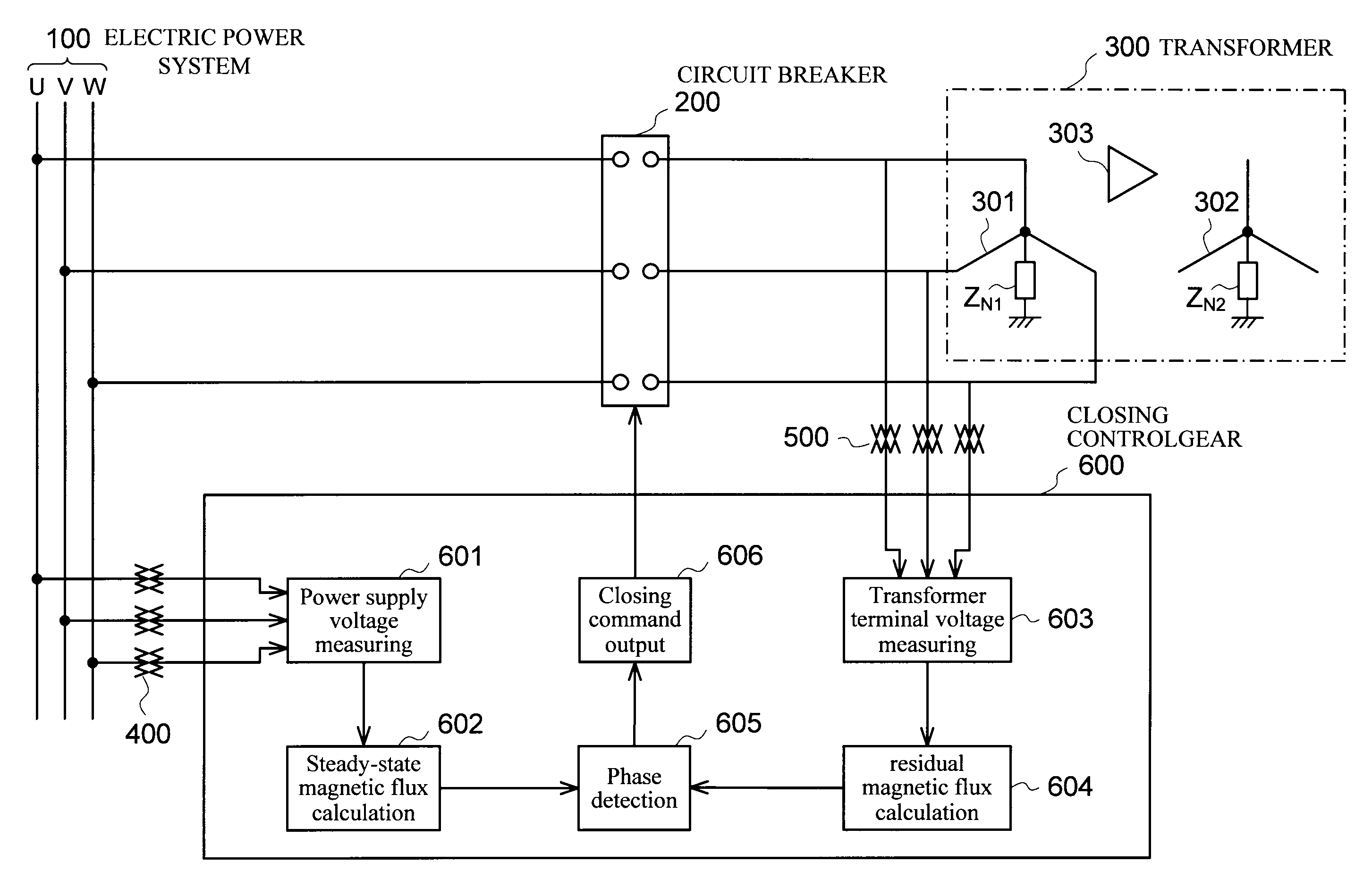
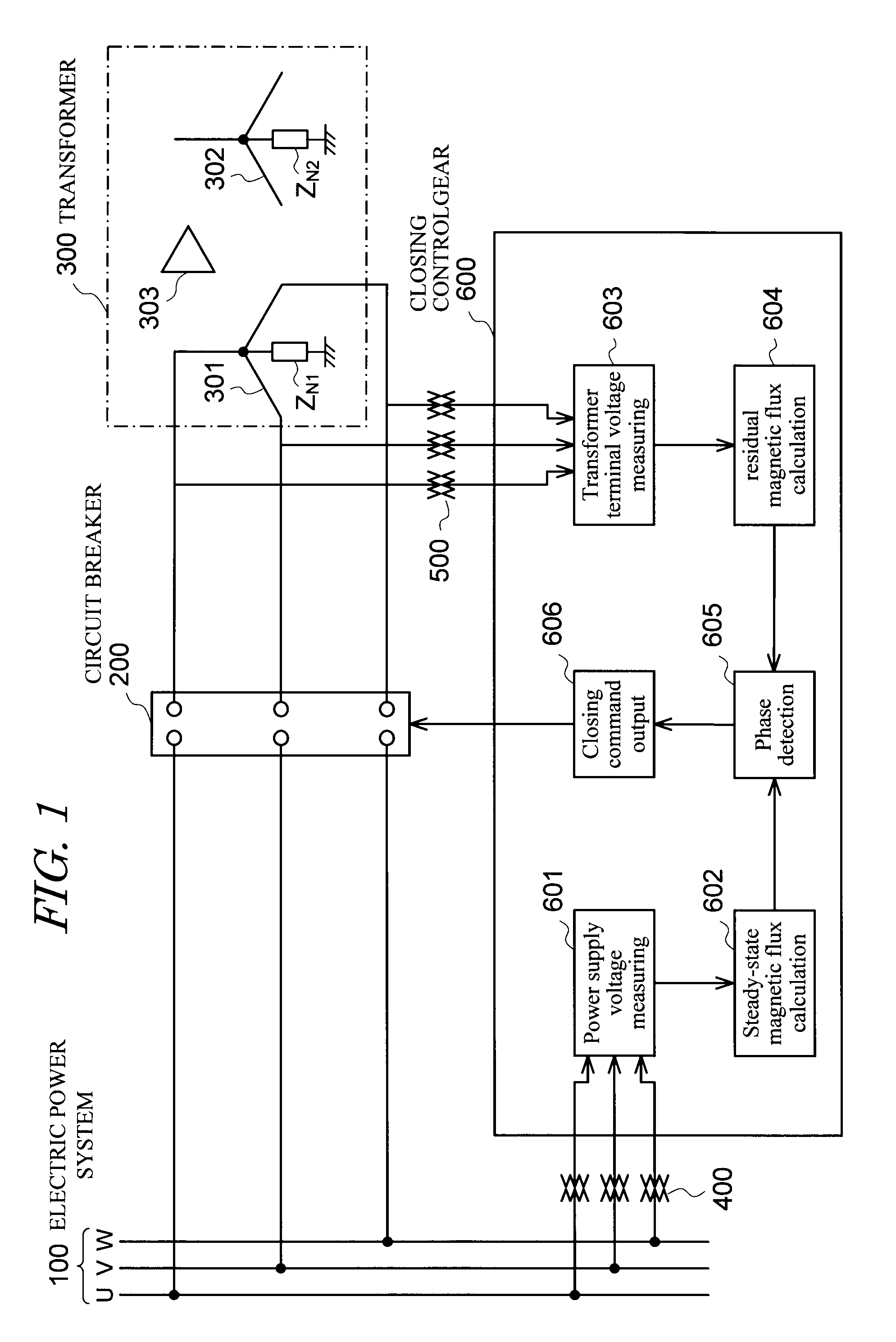
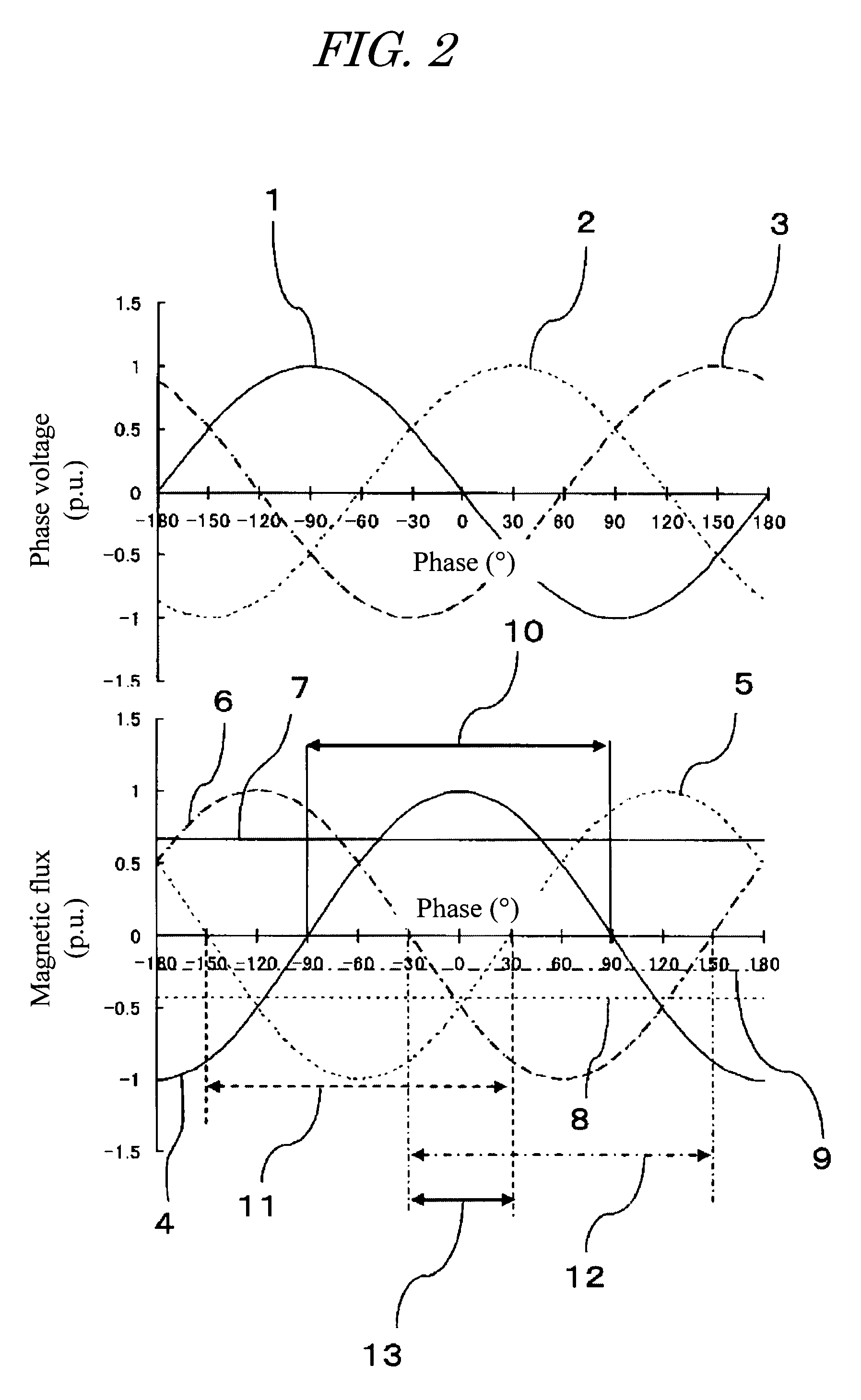
[0081]FIG. 1 to FIG. 4 are provided to explain Embodiment 1; in particular, FIG. 1 is a block diagram showing the connection relation between a three-phase transformer, a three-phase circuit breaker, and a magnetizing inrush current suppression device, FIG. 2 is a waveform diagram showing the relation between the power supply phase voltages, steady-state magnetic flux in the transformer, and residual magnetic flux in the transformer core, FIG. 3 is a waveform diagram showing the residual magnetic flux when a single-phase transformer is supplied with power using a single-phase circuit breaker, the closing phase, and the magnetic flux after supplying power, and FIG. 4 is a waveform diagram showing a case in which the relation between the power supply phase voltages, transformer steady-state magnetic flux, and transformer core residual magnetic flux is different from that in FIG. 1.

(Configuration)

[0082]In FIG. 1, 100 is a busbar of the power system (also called a power supply busbar), ...

embodiment 2

[0104]FIG. 5 to FIG. 7 are provided to explain Embodiment 2; FIG. 5 to FIG. 7 are waveform diagrams showing the relations between the phase voltages, steady-state magnetic flux and residual magnetic flux when energizing a three-phase transformer, and each assume cases in which the manner in which the residual magnetic flux remains is different. In Embodiment 2, the connection relation between the three-phase transformer, three-phase circuit breaker, and magnetizing inrush current suppression device is the same as the case of the above-described Embodiment 1, and so a block diagram corresponding to that ofFIG. 1 is omitted.

(Configuration)

[0105]In Embodiment 2, the closing control device 600 is set such that the closing target point of the three-phase circuit breaker 200 is the point of intersection 22 of the steady-state magnetic flux and the residual magnetic flux for the phase with the smallest residual magnetic flux among the phases of the three-phase transformer 300.

(Action)

[0106...

embodiment 3

[0111]FIG. 8 to FIG. 10 explain Embodiment 3. In particular, FIG. 8 to FIG. 10 are waveform diagrams showing the relation between the phase voltage, steady-state magnetic flux, and residual magnetic flux at the time of energizing of a three-phase transformer; each assume cases in which the manner in which the residual magnetic flux remains is different. In Embodiment 3, the connection relation between the three-phase transformer, three-phase circuit breaker, and magnetizing inrush current suppression device is the same as the case of the above-described Embodiments 1 and 2, and so a block diagram corresponding to that of FIG. 1 is omitted.

(Configuration)

[0112]In Embodiment 3, the closing control device 600 is set such that the closing target point of the three-phase circuit breaker 200 is made the time at which the steady-state magnetic flux is at peak value in the phase with the largest residual magnetic flux at the time of energizing of the three-phase transformer, that is, at the...


PUM


Abstract

To suppress the magnetizing inrush current occurring when supplying power of three phases of the transformer are performed simultaneously using three single-phase circuit breakers or a non-phase segregated operation-type circuit breaker, without providing a circuit breaker with a resistor or other equipment. A magnetizing inrush current suppression method for transformer suppresses a magnetizing inrush current occurring at the start of energizing of a three-phase transformer 300, when a three-phase power supply 100 is input to a terminal of each phase by means of a three-phase circuit breaker 200. In the method, by integrating phase voltages or line-to-line voltages on the primary side or the secondary side or the tertiary side when three-phase AC voltages are applied in a steady state to the transformer 300, steady-state magnetic flux 4, 5, 6 for each phase of the transformer is calculated, and the polarity and magnitude of the residual magnetic flux 7, 8, 9 of each phase of the transformer after the circuit breaker 200 shuts off the transformer are calculated, and the three-phase circuit breaker is caused to close simultaneously in a region 13 in which three phases overlap, each of the three phases having the polarity of the steady-state magnetic flux 4, 5, 6 equal to the polarity of the residual magnetic flux 7, 8, 9 for each phase of the transformer.

Description

TECHNICAL FIELD[0001]This invention relates to a magnetizing inrush current suppression device and method for suppressing the magnetizing inrush current which occurs when a power supply is input to a transformer.BACKGROUND ART[0002]When no-load energizing is performed by supplying power in a state in which there is residual magnetic flux in the transformer core, a large magnetizing inrush current flows. It is widely known that the magnitude of this magnetizing inrush current can be several times the rated load current of the transformer.[0003]When such a large magnetizing inrush current flows, the system voltage fluctuates, and when this voltage fluctuation is large, consumers can be affected.[0004]As a method of the prior art for suppressing magnetizing inrush currents, a magnetizing inrush current suppression method is known in which a circuit breaker with a resistor, formed by connecting in series an closing resistor and a contact, is connected in parallel with any of the circuit...

Claims


Application Information

Patent Timeline
IPC IPC(8): H01H9/56
CPCH02H9/002H01H9/563
Inventor KOSHIDUKA, TADASHISAITO, MINORUNISHIWAKI, SUSUMUTAKAHASHI, NOBUYUKIFUTAGAMI, KOICHISATO, YOSHIMASAKOKUMAI, TSUYOSHIKUSUYAMA, HIROSHI
Owner KK TOSHIBA
Why Eureka
Try Eureka