Recording apparatus

a recording apparatus and recording technology, applied in the direction of printing, other printing apparatus, etc., can solve the problems of insufficient consideration of the technical problem of the existing printer, and the degradation of the recording quality

Active Publication Date: 2010-06-10
SEIKO EPSON CORP
View PDF10 Cites 10 Cited by
  • Summary
  • Abstract
  • Description
  • Claims
  • Application Information

AI Technical Summary

Benefits of technology

[0016]By this configuration, since the plurality of blast sources is included, at least some of the blast sources are displaceable in the width direction of the recordable medium. Since the blast sources are displaced such that the ejection range is changed, it is possible to adjust the gas ejection strength of the blast sources. Accordingly, it is possible to prevent the side end of the recordable medium from floating with more certainty, that is by setting the gas ejection strength from the blast sources disposed at the end of the recordable medium in the width direction to be strong.

Problems solved by technology

If the turbulent flow occurs at an end of the sheet, floating (curling) of the end of the sheet occurs and thus recording quality may deteriorate.
Such a technical problem is not sufficiently considered in the existing printers including the printers of Japanese Patent No. 3075329 and JP-A-2002-292841.

Method used


Image

  • Recording apparatus
  • Recording apparatus
  • Recording apparatus

Examples


first embodiment

[0026]Hereinafter, a first embodiment of the invention will be described with reference to FIGS. 1 and 2.

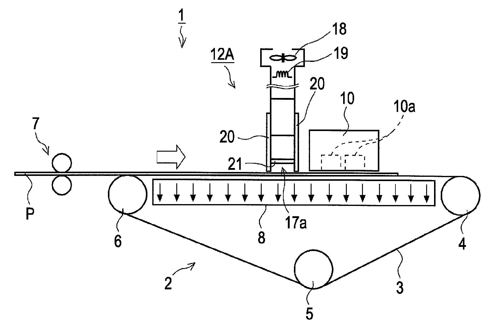
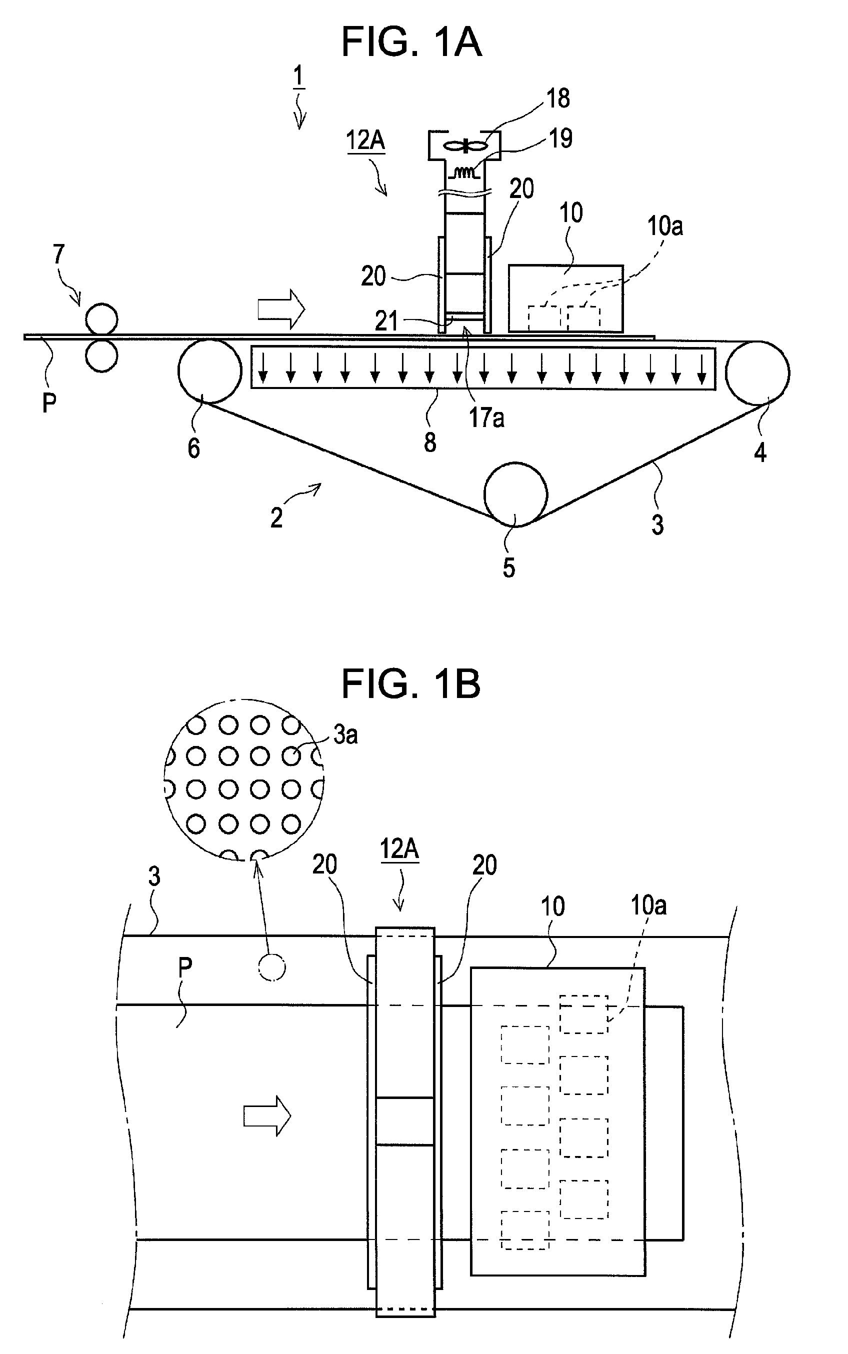
[0027]The printer 1 according to the present embodiment is a so-called line head type high-throughput ink jet printer including an ink jet type recording head (recording unit) 10 with a length covering a sheet width, and ejects inks from the recording head 10 while moving a recording sheet P as an example of a recordable medium in a sheet transportation direction so as to execute recording, without reciprocally moving an ink ejecting head in the sheet width direction.

[0028]In more detail, the printer 1 has a gate roller 7 on the upstream side of a transportation unit 2. By the gate roller 7, skew is eliminated before feeding the recording sheet P to the transportation unit 2 and the recording sheet P is then fed to the transportation unit 2 disposed on the downstream side.

[0029]A transportation belt 3 which forms a transportation surface for transporting the recording sheet P and...

second embodiment

[0042]Hereinafter, a second embodiment of the invention will be described with reference to FIG. 3. In addition, in the following embodiments including the present embodiment, the same configurations as the first embodiment described with reference to FIGS. 1 and 2 are denoted by the same reference numerals and the description thereof will be omitted.

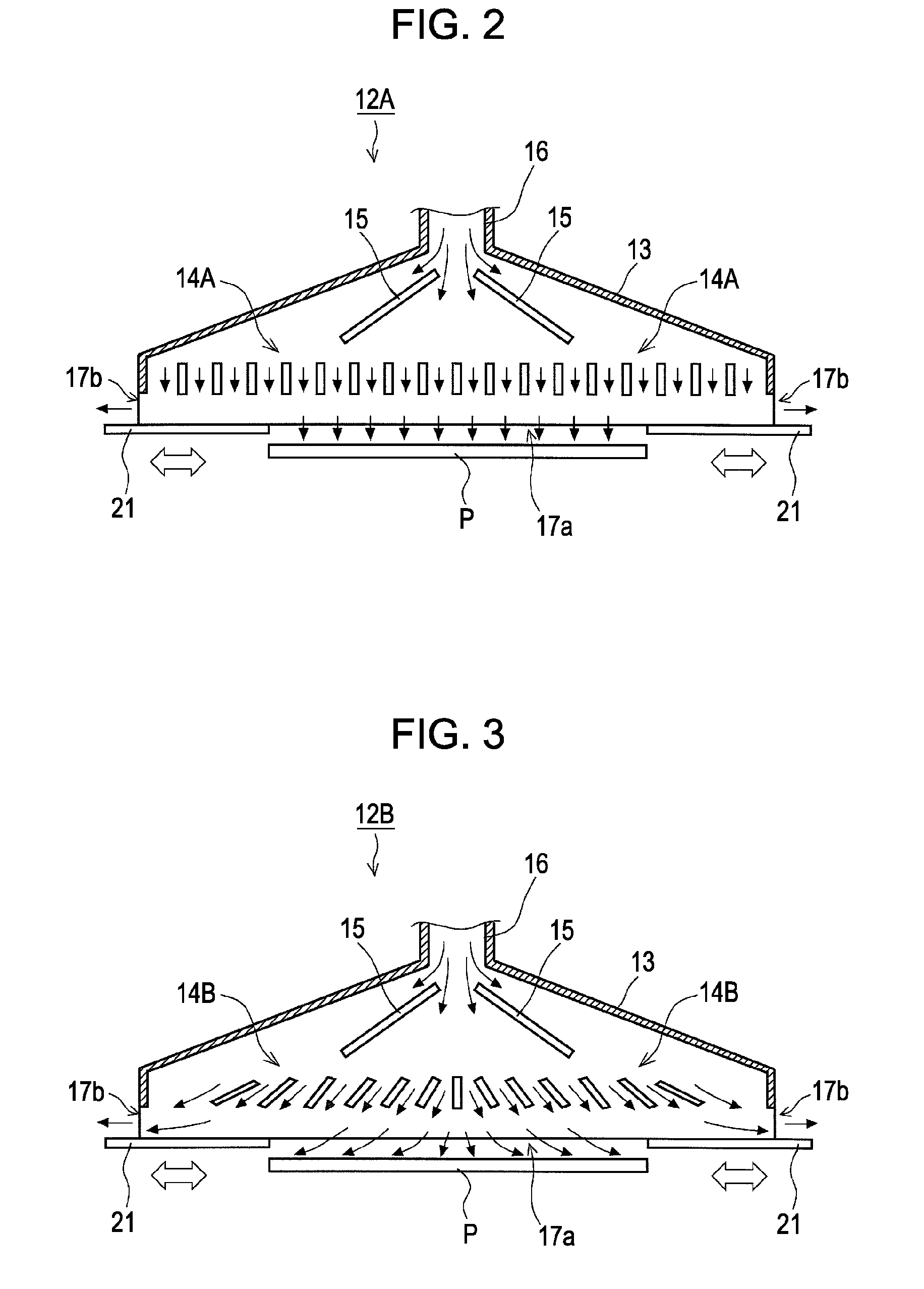
[0043]In the drier 12B according to the present embodiment, the inclined angles of louvers 14B are set to be reduced (lie down to the paper) from the center to the end of the sheet width direction, and air stream is formed from the center to the side end of the sheet in the sheet width direction as denoted by arrows on the paper. Accordingly, air ejected from the drier 12B escapes from the sheet side end outwardly straight. Thus, it is possible to prevent turbulent flow from occurring in the sheet side end and to prevent the sheet side end from floating (curling).

[0044]Since air stream is formed from the center to the side end of the sh...

third embodiment

[0045]Hereinafter, a third embodiment of the invention will be described with reference to FIG. 4. The hot air drier 12C shown in FIG. 4 includes an edge regulating plate 22 for pressing the side end of a sheet. The edge regulating plate 22 is slidably provided in the sheet width direction, and an edge regulation position can be adjusted according to the width of the recording sheet P. Accordingly, even when the turbulent flow of hot air is generated in a region deviated from the end of the sheet, it is possible to prevent the sheet side end from floating (curling) by the turbulent flow with certainty. In addition, the edge regulating plate 22 is applicable to the above-described first and second embodiments or the following other embodiments.


PUM


Abstract

Provided is a recording apparatus including: a recording unit for performing recording on a recordable medium; a transportation unit for transporting the recordable medium; and a drier for accelerating the drying of the recordable medium by ejecting gas to the recordable medium, wherein the drier is configured such that the ejection range of the gas in a direction perpendicular to the transportation direction of the recordable medium is changeable.

Description

BACKGROUND[0001]1. Technical Field[0002]The present invention relates to a recording apparatus such as a facsimile machine or a printer, and more particularly, to a recording apparatus including a drier for accelerating the drying of a recordable medium.[0003]2. Related Art[0004]Hereinafter, a printer will be described as an example of a recording apparatus. In particular, as described in Japanese Patent No. 3075329, there is provided a printer for heating a recording sheet by a heater, evaporating moisture included in the recording sheet, and exhausting air including moisture by an exhauster. JP-A-2002-292841 discloses a printer including a drier for drying an ink landing on a sheet by ejecting hot air onto the sheet.[0005]Even when the heater and the exhauster are included in order to accelerate the drying of the sheet as in the printer described in Japanese Patent No. 3075329 or even when hot air is ejected onto the sheet as in the printer described in JP-A-2002-292841, turbulenc...

Claims


Application Information

Patent Timeline
Patent Type & Authority Applications(United States)
IPC IPC(8): B41J2/01
CPCB41J11/0015B41J2/155
Inventor SHIOHARA, SATORU
Owner SEIKO EPSON CORP
Why Eureka
Try Eureka