
Liquid crystal display, panel therefor, and manufacturing method thereof

Inactive Publication Date: 2010-06-10
SAMSUNG DISPLAY CO LTD
View PDF5 Cites 18 Cited by
  • Summary
  • Abstract
  • Description
  • Claims
  • Application Information

AI Technical Summary

Benefits of technology

[0011]For example, the manufacturing cost is increased when forming the color filters by using additional photolithography steps, such as including inkjet printing. To form the color filters by using inkjet printing, inks of desired amounts of three primary colors such as red, green, and blue are jetted through a plurality of nozzles of an inkjet head, and the jetted inks are filled in regions enclosed by a light blocking member on a substrate. When using the inkjet printing system to form the color filters, repellant power of the ink against the surface of the light blocking member surface is generated such that the color filter is largely formed in the central portion of the region enclosed by the light blocking member as opposed to the edge of the region, and thereby the color filter may have a dome shape. Color filters with the dome shape may undesirably generate light leakage at the edge of pixel areas.
[0012]Additionally, to form the spacers, a photosensitive film is coated on the color filter array panel and is exposed and developed to form column spacers with the desired pattern, and the column spacers are disposed on portions where light is not transmitted, such as at positions corresponding to the channel portion of the thin film transistor, the gate line, and the storage electrode line. When forming the column spacers, additional photolithography steps are executed such that the manufacturing cost is increased by increasing the number of masks, and the manufacturing method of the liquid crystal display becomes complicated.
[0013]If bead spacers are arbitrarily sprayed, the bead spacers may be disposed on the display area of the liquid crystal display such that the light leakage is undesirably generated, thereby decreasing the contrast ratio of the screen. The bead spacers may be slightly moved when combining the two display panels or after combination such that the alignment layers of the display panel may be damaged.
[0014]Exemplary embodiments of the present invention provide a liquid crystal display, a panel therefor, and a manufacturing method thereof having advantages of maintaining a uniform cell gap, including spacers which are not formed at unwanted positions such as the pixel area, eliminating damage of the spacers to the alignment layer of the display panel resulting from movement, forming the spacers without increasing the number of steps of the manufacturing method and manufacturing cost, and including color filters having a substantially flat surface to reduce or effectively prevent light leakage at the pixel edge.
[0038]In an exemplary embodiment of the present invention, the color filter and the spacer are formed through the inkjet printing system such that the spacer may be formed on the desired position without increasing the number of steps of the manufacturing method and the manufacturing cost, and the surface of the color filter formed through the inkjet printing method may be planarized by controlling the height of the light blocking member, thereby preventing the light leakage on the edge of the pixel area.

Problems solved by technology

Where a liquid crystal display includes color filters of three primary colors such as red, green, and blue formed on one display panel, and spacers disposed between facing display panels, thereby maintaining a cell gap between the display panels, there may be technical difficulties and disadvantages in forming the liquid crystal display.
For example, the manufacturing cost is increased when forming the color filters by using additional photolithography steps, such as including inkjet printing.
Color filters with the dome shape may undesirably generate light leakage at the edge of pixel areas.
When forming the column spacers, additional photolithography steps are executed such that the manufacturing cost is increased by increasing the number of masks, and the manufacturing method of the liquid crystal display becomes complicated.
If bead spacers are arbitrarily sprayed, the bead spacers may be disposed on the display area of the liquid crystal display such that the light leakage is undesirably generated, thereby decreasing the contrast ratio of the screen.
The bead spacers may be slightly moved when combining the two display panels or after combination such that the alignment layers of the display panel may be damaged.

Method used


Image

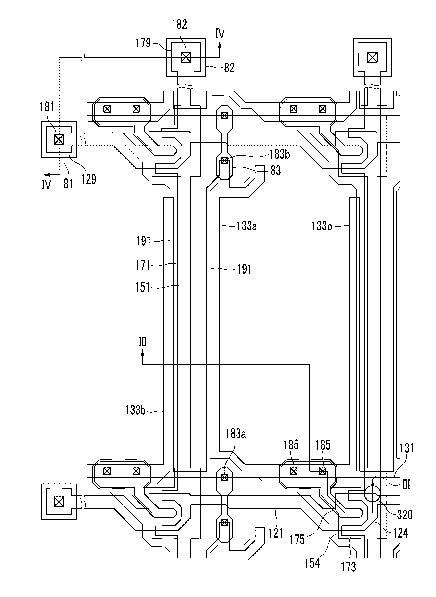
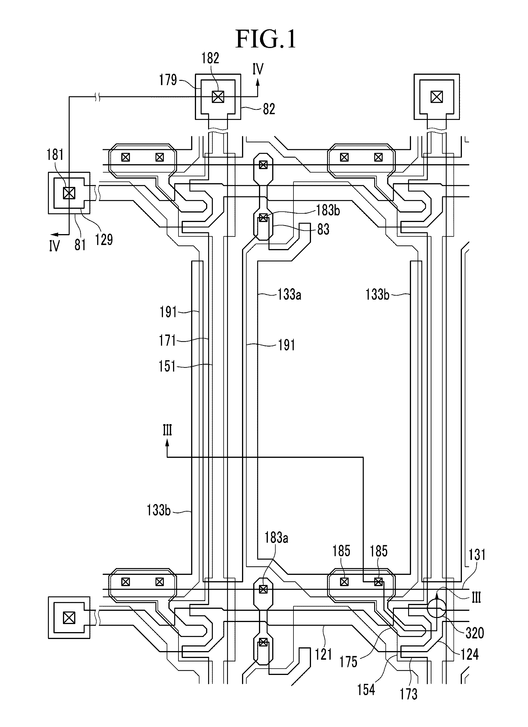
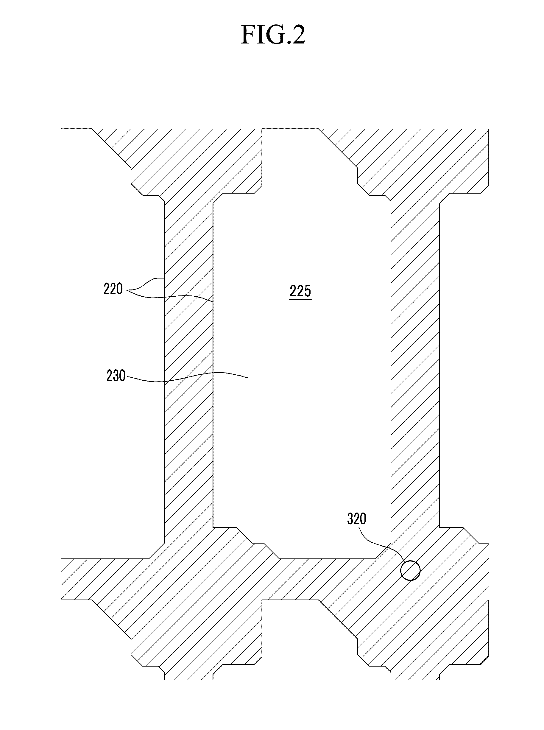
  • Liquid crystal display, panel therefor, and manufacturing method thereof
  • Liquid crystal display, panel therefor, and manufacturing method thereof
  • Liquid crystal display, panel therefor, and manufacturing method thereof

Examples


Embodiment Construction

[0045]The invention is described more fully hereinafter with reference to the accompanying drawings, in which exemplary embodiments of the invention are shown. This invention may, however, be embodied in many different forms and should not be construed as limited to the exemplary embodiments set forth herein. Rather, these embodiments are provided so that this disclosure will be thorough and complete, and will fully convey the scope of the invention to those skilled in the art.

[0046]It will be understood that when an element or layer is referred to as being “on” or “connected to” another element or layer, the element or layer can be directly on or connected to another element or layer or intervening elements or layers. In contrast, when an element is referred to as being “directly on” or “directly connected to” another element or layer, there are no intervening elements or layers present. Like numbers refer to like elements throughout. As used herein, the term “and / or” includes any ...


PUM


Abstract

A display panel includes a substrate, a partition formed on the substrate and defining a plurality of openings, a plurality of color filters formed in the openings and having a substantially uniform thickness within each respective opening, and a spacer formed on the partition. The color filters and the spacer are formed through inkjet printing. The color filters have the substantially uniform thickness by the partition having a height which is greater than the thickness of the color filters during the inkjet printing. The height of the partition may be in a range of about 1.5 to about 2 times the thickness of the color filter.

Description

[0001]This application claims priority to Korean Patent Application No. 10-2008-0124032 filed on Dec. 8, 2008, and all the benefits accruing therefrom under 35 U.S.C. §119, the entire contents of which are incorporated herein by reference.BACKGROUND OF THE INVENTION[0002](a) Field of the Invention[0003]The present invention relates to a display panel for a liquid crystal display, a liquid crystal display, and a manufacturing method thereof.[0004](b) Description of the Related Art[0005]A liquid crystal display includes a pair of display panels provided with field generating electrodes and polarizers, and a liquid crystal layer interposed between the two display panels. The field generating electrodes generate an electric field to the liquid crystal layer, and the arrangement of the liquid crystal molecules is changed according to the change of the intensity of the electric field. The arrangement of the liquid crystal molecules of the liquid crystal layer may be changed while applying...

Claims


Application Information

Patent Timeline
IPC IPC(8): G02F1/1339G02F1/1335G02F1/13
CPCG02F1/133512G02F1/13394G02F1/133516G02F1/133514G02F1/13G02F1/1335
Inventor SHIM, YI-SEOPLEE, KWANG-HOKIM, JIN-SEUKKIM, JANG-SUBKANG, YOON-HOMIN, TAE-GEEKWON, SEONG-GYUKWAK, CHANG-HUNKIM, JAE-HOONYU, JAE-JUN
Owner SAMSUNG DISPLAY CO LTD
Learn More