Reinforcing fibrous structure for a composite material and a part containing said structure

a fiber structure and composite material technology, applied in weaving, other domestic articles, transportation and packaging, etc., can solve the problems of affecting the quality of the composite material, and affecting the mechanical properties of such parts

Active Publication Date: 2010-06-10
GERAKL
View PDF5 Cites 44 Cited by
  • Summary
  • Abstract
  • Description
  • Claims
  • Application Information

AI Technical Summary

Benefits of technology

[0016]When the fiber structure is densified by CVI to obtain a composite material part, an interlock weave in the core ensures easier access for the infiltration to the core of the preform.
[0017]Weaving at the skin with a satin type weave serves to limit surface irregularities. When densification is performed with a resin, this avoids clumps of resin forming on the surface, of the kind that can be observed with an interlock weave such as that in above-mentioned document EP 1 526 285 for which surface irregularities are relatively large. The weaving at the skin may be a multilayer weave, or it may be a two-dimensional weave, in which case weaving with an interlock weave serves to bond the layers together and extends into a portion of the skin.
[0022]Furthermore, at least one of the warp and weft counts can be caused to vary between the core and the skin, for example by reducing the count between the core and the skin so as to give easier access for infiltration through the skin into the core while the fiber structure is being densified by CVI.
[0027]With these features, it is possible to provide three-dimensional weaving continuity into portions of a fiber structure that are very thin, for example the portions of fiber preforms for turbomachine blades that correspond to the trailing edges of the blades.
[0028]It is also possible to form the various portions of the fiber structure with yarns presenting different chemical natures so as to give them desired particular properties, in particular the ability to withstand wear or oxidation.

Problems solved by technology

In addition, for composite material parts having a resin matrix, the presence of significant surface irregularities leads to the formation of localized clumping of the resin, thereby harming the mechanical properties of such parts.
When access to the pores within the fiber structure is difficult, or when there are pores presenting sizes that are very different, with the smaller pores becoming closed up more quickly, then a steep densification gradient is inevitable, and that affects the properties of the composite material.

Method used


Image

  • Reinforcing fibrous structure for a composite material and a part containing said structure
  • Reinforcing fibrous structure for a composite material and a part containing said structure
  • Reinforcing fibrous structure for a composite material and a part containing said structure

Examples


example 1

Not Covered by the Claims

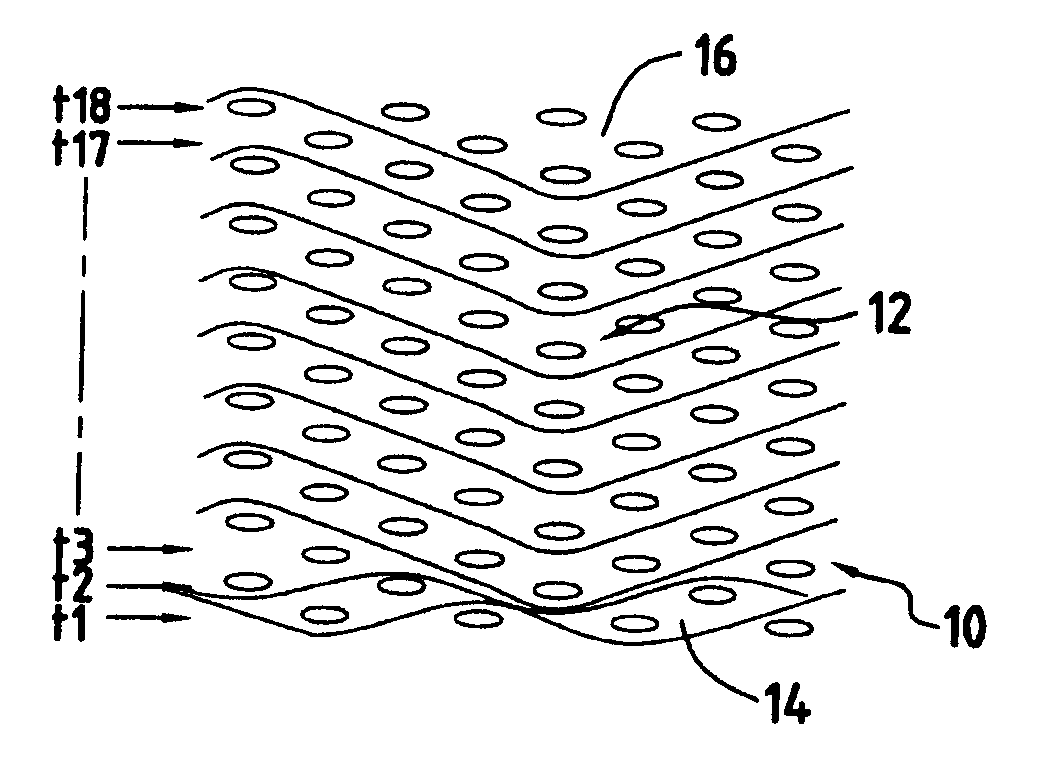
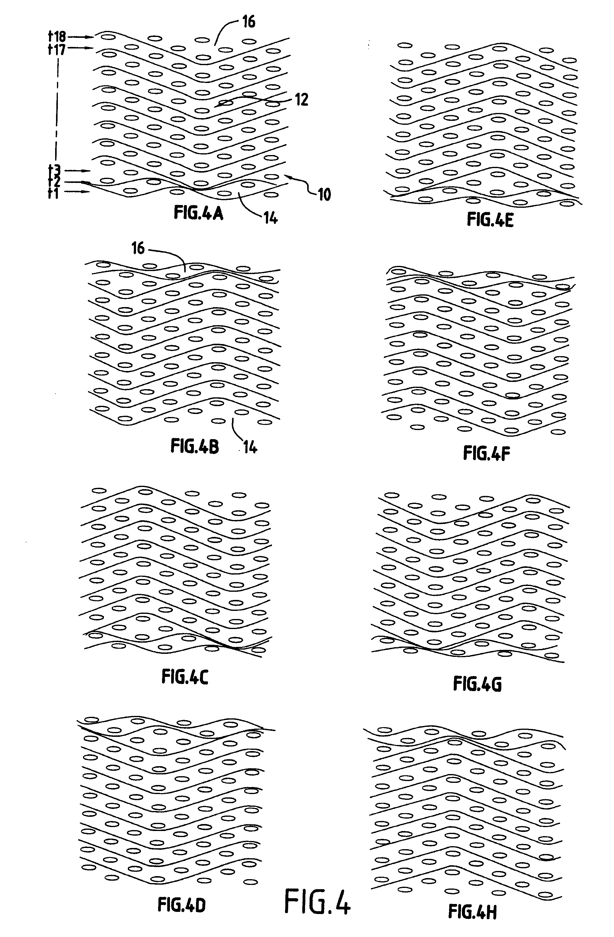
[0066]FIGS. 4A to 4H show portions of eight successive planes of a fiber structure weave obtained by 3D weaving, the weft yarns being visible in section.

[0067]The fiber structure 10 comprises nine weft yarn layers, i.e. eighteen half-layers t1 to t18. In the core 12 situated between two opposite skins 14 and 16, the 3D weaving is of the interlock type with a 10 / 10 count per layer (ten yarns per centimeter in the weft and warp directions). In the skins 14 and 16, the weaving is two-dimensional with a plain type weave with a 5 / 5 count per layer. The plain weave applies only to half-layers t1 and t2 and to half-layers t17 and t18 of weft yarns. It should be observed that the 3D interlock weave of the core extends to the outermost half-layers t1, t18 of the skins so as to bond these half-layers to the core layers.

[0068]In this example, the methods of weaving and the counts vary between the core and the skins. The plain weave skin encourages obtaining a surface s...

example 2

[0069]FIGS. 5A to 5H show successive planes of a fiber structure weave 20 obtained by 3D weaving, said structure differing from that of Example 1 in that in the skins 24, 26, the weaving is a satin weave with a 5×5 count and involves only the outermost half-layers of weft yarns t1 and t18, while the weave of the core 22 is of the interlock type with a 10×10 count per layer.

[0070]In this example, the method of weaving varies between the core 22 and the skins 24, 26, the skin satin weave giving a smooth surface appearance.

example 3

[0071]FIGS. 6A to 6J show a portion of the successive planes of a fiber structure 50 obtained by 3D weaving, using an interlock weave in the core 52 and a multilayer weave at the skin. The interlock weave is made with each warp yarn extending over a depth of two half-layers of weft yarn. The multilayer weave at the skin 56 is made with a multiple satin type weave having a pitch of 5, uniting an external weft layer formed by two half-layers with an adjacent weft half-layer.

[0072]Only a portion of the weave is shown, it being possible to increase the number of weft layers as represented by dashed lines, and the skin opposite to the skin 56 not being shown, the weave of said opposite skin possibly being of the same type as that of the skin 56.


PUM

PropertyMeasurementUnit
temperaturesaaaaaaaaaa
thicknessaaaaaaaaaa
structureaaaaaaaaaa

Abstract

A woven fibrous structure embodied in one piece, used for producing a composite material part and comprising an internal part or a core (72) and a part adjacent to the external surface thereof or a skin (74, 76), is formed by three-dimensional core weaving with at least one weave selected from interlock and multilayer weaves and by skin weaving with a weave which differs from the core weave and selected from a multilayer weave and a two-dimensional weave. It can be also formed by three-dimensional weaving with at least one core interlock weave (72) and weaving with a fabric-, satin or skin twill-type weave, wherein skin weaving is of a multilayer or two-dimensional type.

Description

BACKGROUND OF THE INVENTION[0001]The invention relates to making composite material parts, and more particularly to making reinforcing fiber structures for such parts.[0002]The field of application of the invention is making structural parts of composite material having fiber reinforcement and a resin matrix. Such parts are used in very many fields, and in particular in the field of aviation. One particular example is making blades for turbomachines, in particular fan blades. The reinforcing fiber structure is densified by a resin matrix in any known manner, for example by resin transfer molding (RTM).[0003]Another field of application for the invention is making parts out of thermostructural composite material, i.e. a material having mechanical properties that makes it suitable for constituting structural elements and also having the ability to conserve these properties at high temperatures. Thermostructural composite materials are typically carbon / carbon (C / C) composite materials ...

Claims


Application Information

Patent Timeline
Patent Type & Authority Applications(United States)
IPC IPC(8): D03D11/00B29C70/20B29C70/34B64C25/02
CPCB29C70/24B29C70/48B29L2031/3076Y10T74/2142D03D25/005F16C7/026B64C25/12B29L2031/7488F16C2326/43Y10T442/3195Y10T442/3211Y10T442/3203B29B11/16F16C7/02
Inventor COUPE, DOMINIQUEDAMBRINE, BRUNOMAHIEU, JEAN NOELBOUILLON, ERICCHARLEUX, FRANCOIS
Owner GERAKL
Why Eureka
Try Eureka