Smes system, interface device for smes and driving method thereof

a technology of superconducting coils and interface devices, applied in the direction of superconducting magnets/coils, electrical storage systems, magnetic bodies, etc., can solve the problems of high loss, high loss upon holding the electric current in a standby condition, and difficulty in safely reducing the electric current of the superconducting coil and holding the electric current necessary for protecting the coil device. , to achieve the effect of reducing the loss upon the current holding operation of the smes

Inactive Publication Date: 2010-06-10
MITSUBISHI HEAVY IND LTD
View PDF4 Cites 5 Cited by
  • Summary
  • Abstract
  • Description
  • Claims
  • Application Information

AI Technical Summary

Benefits of technology

[0016]Therefore, an object of the present invention is to provide a superconducting magnetic energy storage system, in which a loss is lower in a current hold mode.
[0017]Another object of the present invention is to provide a superconducting magnetic energy storage system, which is capable of holding an electric current of a superconducting coil in safety and is capable of reducing the electric current by a simple protection circuit in the case where a trouble occurs in a current-voltage converter or a power source of an electric power system breaks down.
[0018]Still another object of the present invention is to provide a superconducting magnetic energy storage system including an aggregate device provided with a plurality of superconducting coils, which is capable of holding electric currents of the superconducting coils in the case where a trouble occurs in the current-voltage converter and in the case where a power source of the electric power system breaks down; and is capable of preventing lowering of a characteristic of a superconducting wire material, excessively increasing the electric current, and generating excessive electromagnetic power between coils due to errors of the distribution of magnetic fields.
[0029]According to the present invention, it is possible to reduce the loss upon the current holding operation of the SMES.

Problems solved by technology

Particularly, in the use of power storage, these losses become higher since the self turn off element having the higher-speed operation and the higher reverse withstand voltage is required.
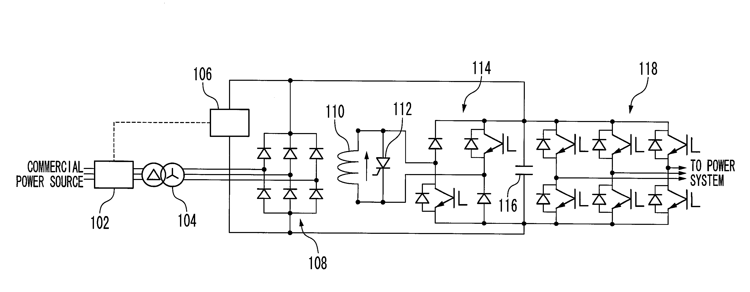
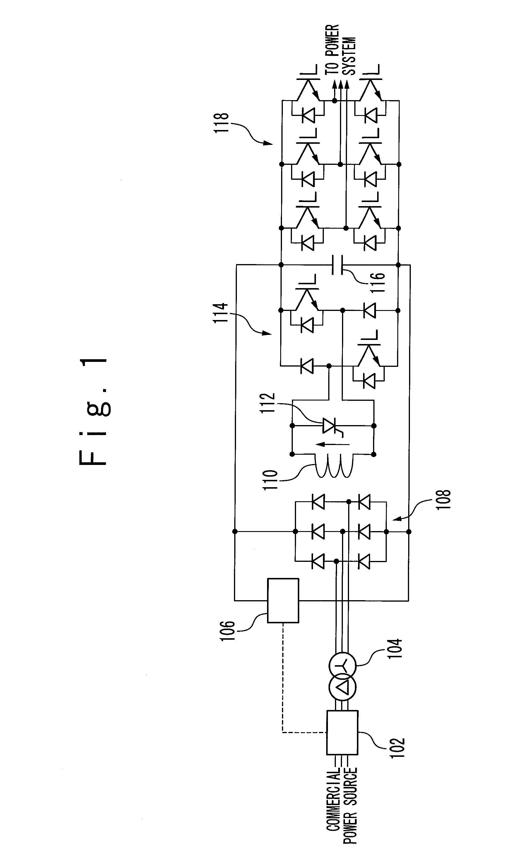
Further, a plurality of elements including a diode is connected in series in order to configure the circuit, so that there is a problem such that a loss upon holding the electric current in a standby condition is higher.
Further, in such a circuit, in the case where a trouble occurs in the current-voltage converter and in the case where a power source of the electric power system breaks down, it is hard to safely reduce an electric current of the superconducting coil and hold the electric current necessary for protecting the coil device.
Moreover, in the case where the trouble occurs in the current-voltage converter and in the case where the power source of the electric power system breaks down, in the circuit shown in FIG. 1, it is not possible to carry out the holding operation for holding the electric current of the superconducting coil.
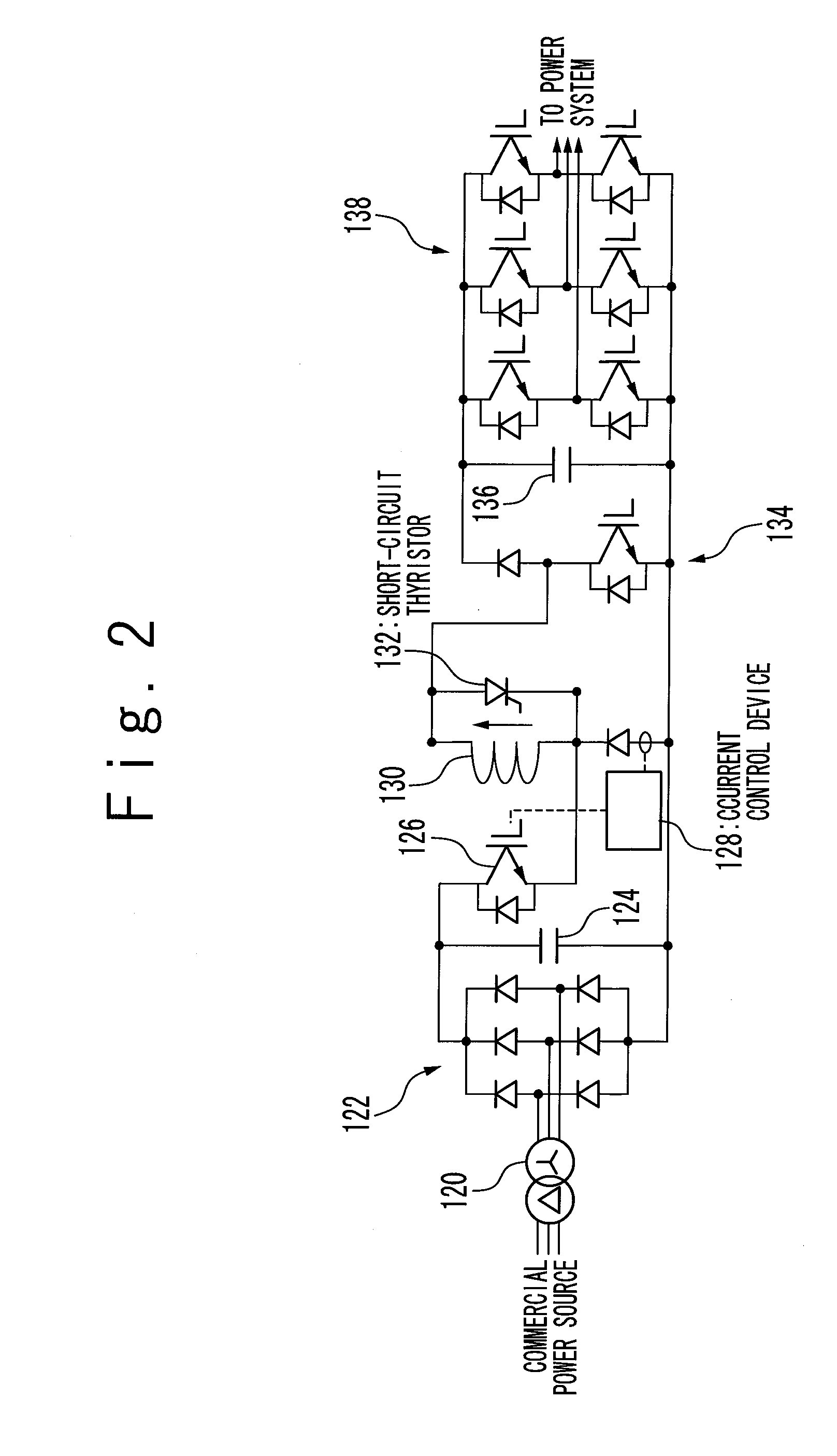
Therefore, in the case of an aggregate device provided with a plurality of superconducting coils, due to an error of magnetic field distribution, a characteristic of a superconducting wire material is lowered, the electric current is excessively increased, and excessive electromagnetic power is generated between coils.
Therefore, there is a possibility that this is detrimental to maintenance, check, and repair of the SMES system.

Method used


Image

  • Smes system, interface device for smes and driving method thereof
  • Smes system, interface device for smes and driving method thereof
  • Smes system, interface device for smes and driving method thereof

Examples


Embodiment Construction

[0036]Referring to the drawings, a superconducting magnetic energy storage system (the SMES system) according to the present invention will be described below. FIG. 3 is a circuit diagram showing a circuit configuration of the SMES system according to an embodiment of the present invention. Referring to FIG. 3, the SMES system includes a superconducting coil 20. The superconducting coil 20 serves as a coil to store electric power due to circulation of an electric current in a superconducting state. One end of the superconducting coil 20 is connected to an anode of a diode D8 of a current-voltage bidirectional converter 16 and a collector of an Insulated Gate Bipolar Transistor (IGBT) element T7 via one switch of a disconnect switch 18. The other end of the superconducting coil 20 is connected to a cathode of a diode D7 of the current-voltage bidirectional converter 16 and an emitter of an IGBT element T8 via the other switch of the disconnect switch 18. Free wheeling diodes are conn...


PUM

PropertyMeasurementUnit
superconductingaaaaaaaaaa
AC currentaaaaaaaaaa
DC currentaaaaaaaaaa

Abstract

A loss can be reduced upon a current holding operation of a SMES. A superconducting magnetic energy storage (SMES) system includes a loop composed of a superconducting coil, a thyristor, and a synchronous rectification circuit, and a loop current flow through the loop. In a loop current hold mode, a switching control device of the synchronous rectification circuit turns on the thyristor, and the synchronous rectification circuit compensates for the loop current by rectifying an AC current from an AC power source to generate a DC current.

Description

[0001]INCORPORATION BY REFERENCE[0002]This application claims a priority from Japanese patent application No. 2008-291374 under the Paris Convention. The disclosure of which is incorporated herein in its entirety by reference.TECHNICAL FIELD[0003]The present invention relates to a superconducting magnetic energy storage system.BACKGROUND ART[0004]As an electric power storage system for storing electric power and discharging the electric power in response to a request, a Superconducting Magnetic Energy Storage (SMES) has been developed. By the flow of an electric current through a superconducting coil in a superconducting state, the electric power is stored in the SMES. Supply of the electric power to the superconducting coil and discharge of the electric power from the superconducting coil are carried out via a converter, which converts the electric power between the SMES and an AC power source of an electric power system.[0005]FIG. 1 shows a charge and discharge circuit of a conven...

Claims


Application Information

Patent Timeline
Patent Type & Authority Applications(United States)
IPC IPC(8): H01F6/06
CPCH02J3/185H02J15/00Y02E40/67Y02E40/24Y02E40/10Y02E40/20Y02E40/60
Inventor KAWASHIMA, HIROSHI
Owner MITSUBISHI HEAVY IND LTD
Why Eureka
Try Eureka