Container vessel stowage planning

Inactive Publication Date: 2010-06-10
A P MOLLER AS
View PDF0 Cites 35 Cited by
  • Summary
  • Abstract
  • Description
  • Claims
  • Application Information

AI Technical Summary

Benefits of technology

[0016]Embodiments of the present invention are based on the realisation that container vessel stowage planning is indeed tractable by a computer-implemented method and—despite the beliefs expressed in the prior art—does not necessarily become harder with the vessel size. There are several reasons for this: Firstly, it is the density of constraints rather than the size of the combinatorial space that determines how hard a combinatorial problem is. Secondly, the NP-hardness result of Avri

Problems solved by technology

The generation of optimized stowage plans is a complex problem which previously has been performed manually by stowage coordinators.
Thus, the time required by known algorithms for solving the problem has been expected to grow exponentially or worse with the problem size.
Moreover if we ignore that some stowage plans may be invalid, it is clear that the number of stowage plans is extremely large even for small vessels.
Due to this, most researchers and practitioners believe that container vessel stowage planning is a very hard combinatorial problem and that the hardness of the problem grows fast with the size of the vessel.
Non-hierarchical methods are only fast enough to be used in practice by coord

Method used


Image

  • Container vessel stowage planning
  • Container vessel stowage planning
  • Container vessel stowage planning

Examples


Embodiment Construction

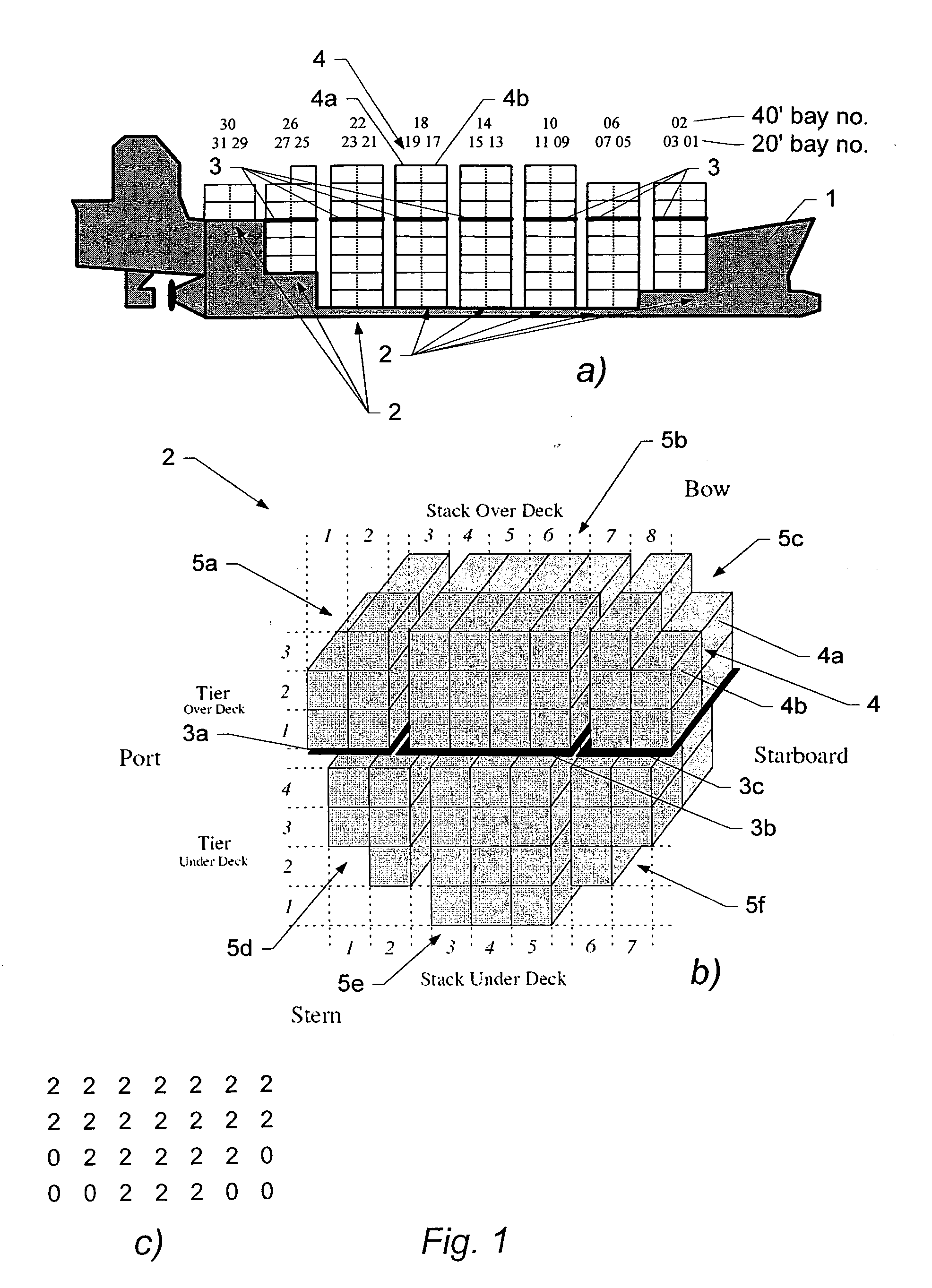
[0065]FIG. 1 schematically illustrates an example of storage areas and cargo item positions on a vessel. A container vessel 1 typically includes of a number of bays 2 where single rows of 40′ or 45′ containers or double rows of 20′ containers can be stacked (these may be referred to as 20′ and 40′ bays, respectively). For example, position 4 can hold a single 40′ or 45′ container or two 20′ containers as illustrated by reference numerals 4a and 4b. FIG. 1a shows a typical numbering of the container stacks in the bays where even numbers are used for 40′ bays while odd numbers are used for 20′ bays. A number of hatch covers 3a-c divide the bays into under and over deck positions. FIG. 1b shows a schematic view of an example of the positions of a bay 2. This example assumes that there are three hatch covers 3a-c: one in the centre 3b and one in each side. It will be understood, however, that the number and arrangement of hatch covers may vary from vessel to vessel. Each level of contai...


PUM


Abstract

A computer-implemented method of determining an allocation plan for a cargo stowage problem of allocating a set of cargo items to a set of cargo item positions of a vessel, each cargo item position being suitable for receiving a cargo item. The method comprises constructing an expression indicative of one or more constraints to be satisfied by said allocation plan, constructing a cost function indicative of a cost of an updated allocation plan relative to a current allocation plan of said cargo stowage problem, iteratively updating a current allocation plan from an initial allocation plan to an updated allocation plan so as to decrease said cost function under said one or more constraints.

Description

BACKGROUND[0001]In modern container transport, a container vessel typically serves / calls a sequence of ports, typically a cyclic sequence of ports. Such a cyclic sequence of ports that a vessel calls will also be referred to as a string, and each voyage of the vessel is referred to as a round-trip (or rotation) through the ports.[0002]A container vessel typically accepts containers at each port of call which are destined for respective ones of the other ports of call that the ship is due to visit. At each port of call, the vessel discharges all of the containers destined for that port and it loads all the containers which are destined for other ports of call which the ship is due to visit.[0003]There are a large number of different types of containers that are transported by container vessels. Typically, standard containers are either 20′ or 40′ long, 8′ wide, and 8′6″ high. The capacity of a container vessel is normally measured in twenty feet equivalent units (TEU) or forty feet e...

Claims


Application Information

Patent Timeline
IPC IPC(8): G06F7/00G06Q10/00G06Q50/00
CPCG06Q10/067G06Q10/103G06Q10/08
Inventor GUILBERT, NICOLASPAQUIN, BENOIT
Owner A P MOLLER AS
Why Eureka
Try Eureka