
Vehicle Guidance System

Active Publication Date: 2010-06-10
ULTRA GLOBAL
View PDF13 Cites 30 Cited by
  • Summary
  • Abstract
  • Description
  • Claims
  • Application Information

AI Technical Summary

Benefits of technology

[0006]It is an advantage of the invention that the memory can store a number of predetermined paths, one of which can be selected by a user travelling in the vehicle.
[0007]It is a further advantage of the invention that the vehicle guidance system can be used in a vehicle for use in any travel network, by storing the predetermined paths specific to the desired network in the memory.
[0008]The term “steering system” is intended to include any type of mechanism, device or control device, which is capable of steering or directing a vehicle along a path in response to an output or control signal from a control means, including a computer. In a preferred embodiment, the vehicle is a wheeled vehicle and the steering system comprises steerable wheels and a steering mechanism that controls the steering direction of the steerable wheels.
[0009]The sensor may be one of a plurality of sensors. For example, four sensors may be provided, each positioned substantially at or near a corner of the vehicle, and directed laterally of the longitudinal axis of the vehicle. Preferably two sensors are provided on each side of the vehicle, which are spaced apart sufficiently to detect any angular change in the position of the central axis of the vehicle relative to a substantially straight reference surface.
[0010]The or each sensor may be anon-Contact sensor, such as an ultrasonic, laser, radar or any other suitable sensor for sensing distance.
[0011]The vehicle guidance system may comprise a trackway on which the vehicle runs. The trackway may be bounded by curbs laid on each side of the trackway. The curbs may provide the reference surface, which is sensed by the sensors. The term “trackway” is intended to include any track, roadway or surface, dedicated or otherwise, over which the vehicle may run. In a preferred embodiment, the system comprises a trackway having a generally flat running surface for the vehicle, bounded laterally by curbs or other elevated structures. The trackway may for example, be constructed in accordance with British Patent Specification 2384223.

Problems solved by technology

The vehicles follow the tracks without any on-board steering control and cannot make a journey to a destination in the network, without the points being arranged specifically for that journey.
Typically, the vehicle slavishly follows the track, and is limited to the route specifically provided for by the track.

Method used


Image

  • Vehicle Guidance System
  • Vehicle Guidance System
  • Vehicle Guidance System

Examples


Embodiment Construction

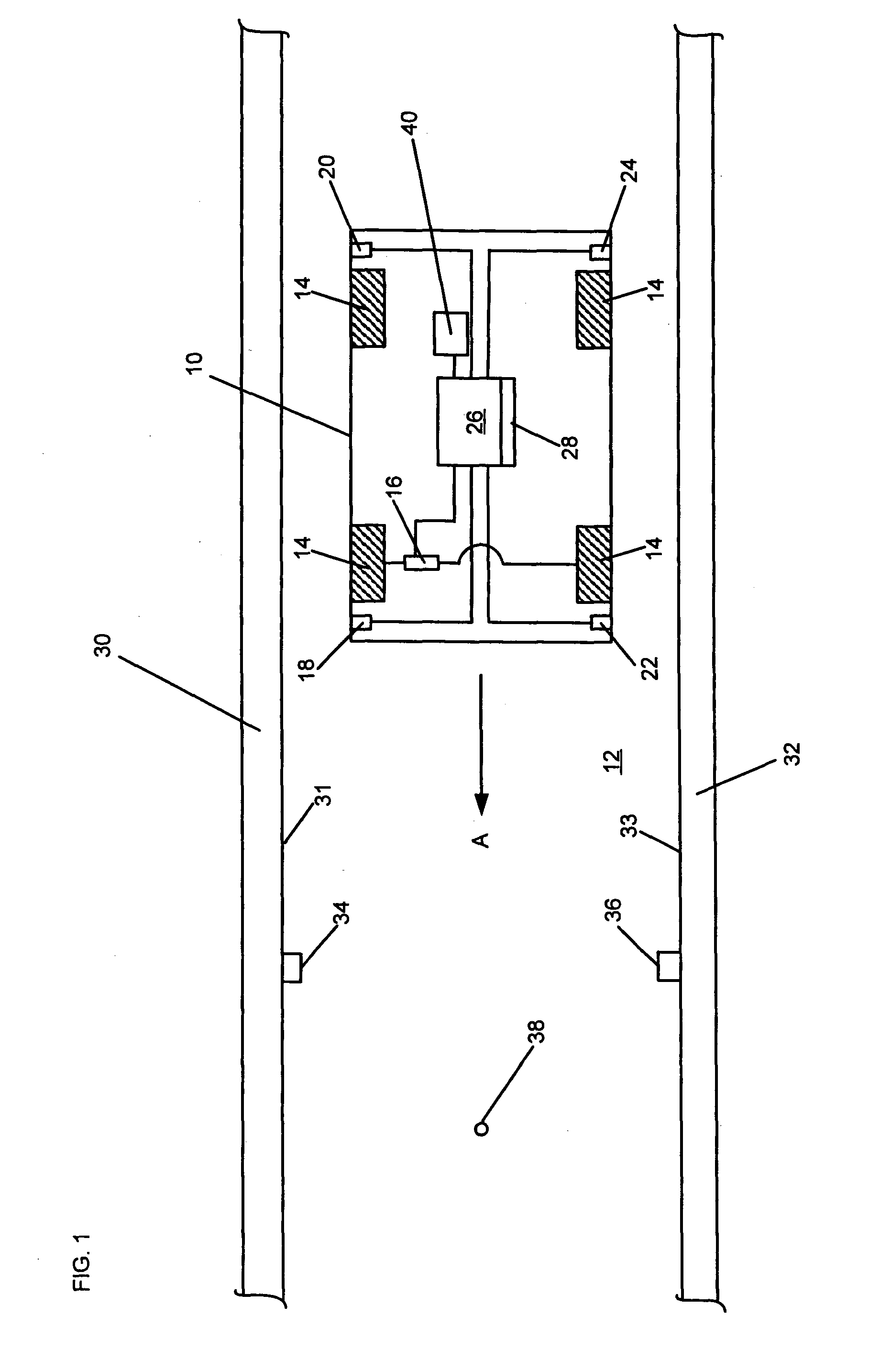
[0027]Referring to FIG. 1, an unmanned personal rapid transit (PRT) vehicle 10 is shown travelling along a trackway 12. Although only a short length of straight trackway is shown, this preferably forms part of a PRT network, comprising a plurality of vehicles and a plurality of stations connected by the trackway. The system may include junctions between trackway sections. Preferably, the stations are situated off the main trackway, so that vehicles of the system travel along the main trackway between the originating and destination stations for each journey, without needing to stop at intermediate stations.

[0028]The vehicle 10 has four wheels 14, two of which steer the vehicle, by means of a steering system, indicated at 16. One or more of the wheels 14 is driven, for example by an electric motor powered by an onboard power supply such as a battery. An ultrasonic distance sensor 18, 20, 22, 24 is positioned substantially at or close to each of the four corners of the vehicle 10. Two...


PUM


Abstract

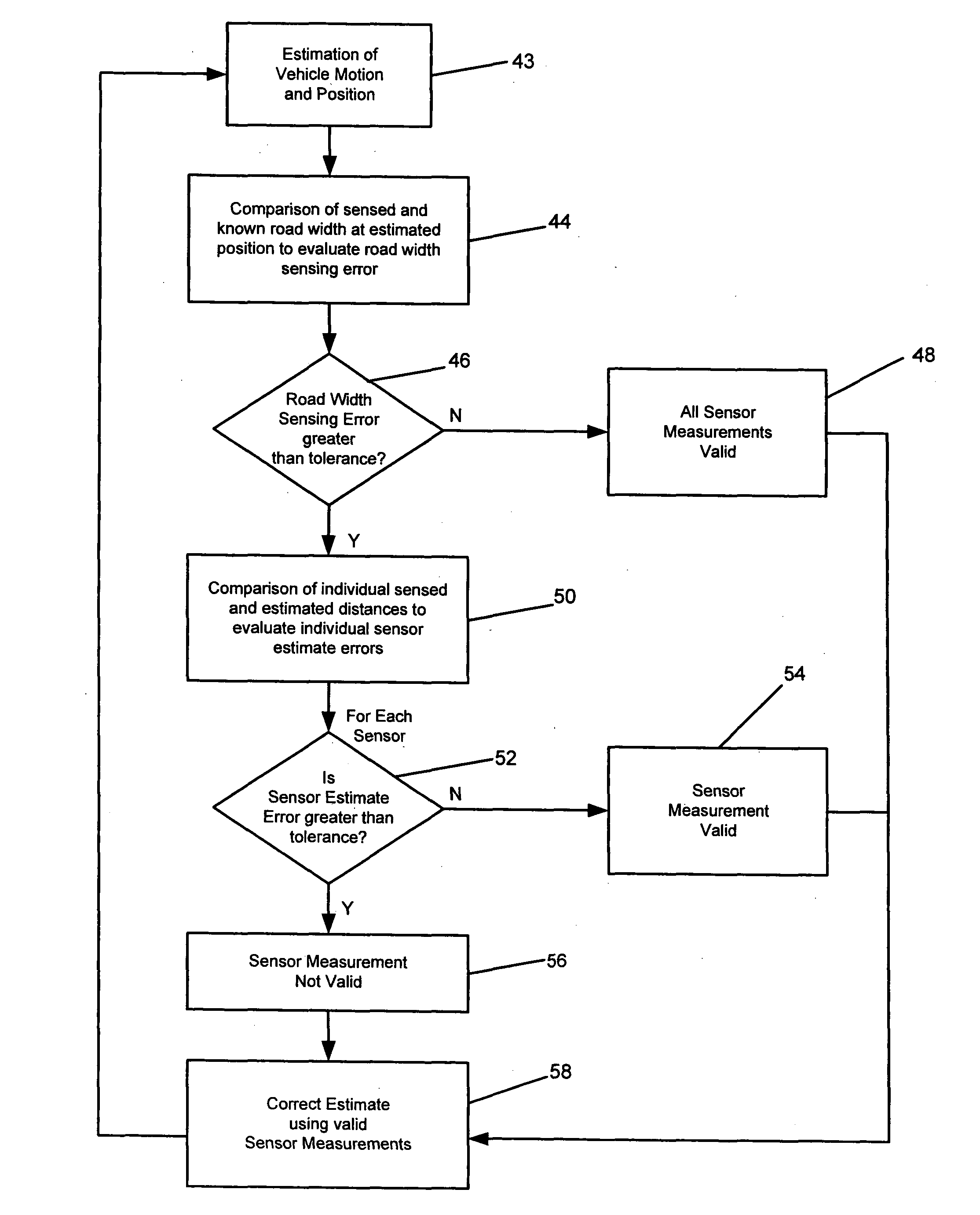
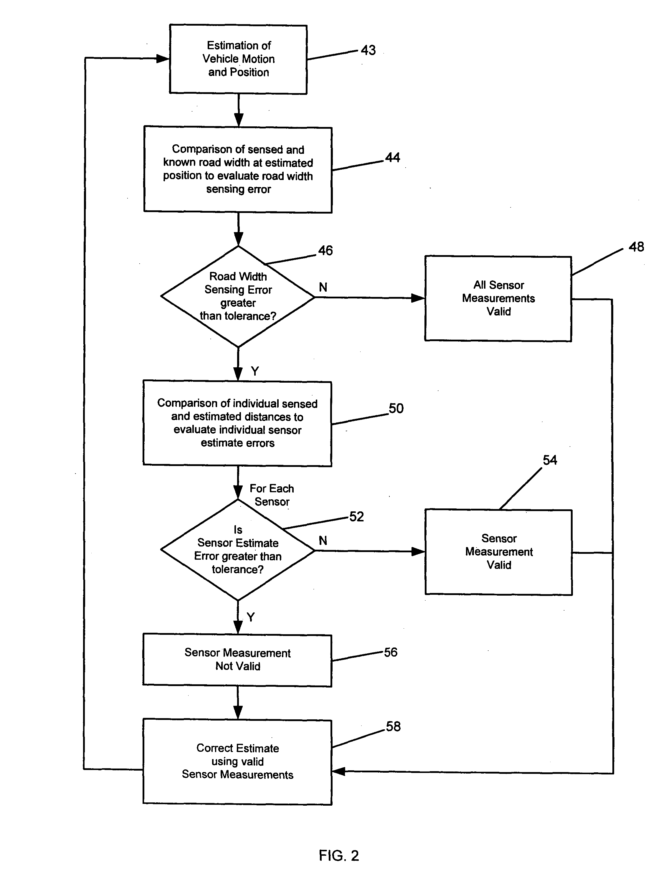
A vehicle guidance system for directing a vehicle along a predetermined path comprises an onboard computer, a number of distance sensors and a steering system controllable by the computer. The predetermined path is stored in a memory of the computer and, in operation, the steering system is controlled to follow the predetermined path. The sensors are adapted to measure the distance, laterally of the vehicle travel direction, between the sensors and curbs provided along the predetermined path, and the computer is adapted to control the steering system to correct any lateral deviation from the predetermined path as detected by the sensors.

Description

BACKGROUND OF THE INVENTION[0001]This invention relates to a vehicle guidance system, and particularly but not exclusively to a vehicle guidance system for an unmanned personal rapid transit (PRT) vehicle.[0002]In general, a personal rapid transport (PRT) system comprises a dedicated track on which individual vehicles travel between stations. Each vehicle contains only one passenger or group of passengers, and the vehicle travels continuously between the starting point and the destination without stopping at any intermediate stations. PRT systems thus provide a compromise between a conventional mass transport system such as buses, trains and metro systems, and individual passenger cars.[0003]It is known to provide an unmanned vehicle or driverless vehicle suitable for travelling on rails, such as monorail or dual rails used in conventional railway construction. The railway track is usually part of a network of track, and to travel from one destination to another, points at the junct...

Claims


Application Information

Patent Timeline
IPC IPC(8): G05D1/00B62D6/00B61B13/00
CPCG05D1/0234G05D1/024G05D2201/0212G05D1/0257G05D1/0272G05D1/0255B62D1/28G01S2013/9318G05D1/02
Inventor ROSS-MARTIN, TORQUIL
Owner ULTRA GLOBAL
Learn More