
Tightening device with swivelling handling arm and appliance including such a device

a technology of tightening device and handling arm, which is applied in the direction of metal sawing device, sawing device, metal sawing apparatus, etc., and can solve the problems of simple operation and fastness

Active Publication Date: 2010-06-17
PELLENC SA
View PDF15 Cites 26 Cited by
  • Summary
  • Abstract
  • Description
  • Claims
  • Application Information

AI Technical Summary

Benefits of technology

[0015]According to the invention, this aim has been achieved thanks to a tightening device of the screw-nut kind, comprising a tightening member that can be rotated and a driving wrench of this tightening member equipped with a handling arm. This wrench and tightening member are joined by a connecting device contrived in such a way that the wrench can swivel in relation to the tightening member around a swivel axis that is perpendicular to the screwing axis of said tightening member, so as to allow its placement in a rest position essentially perpendicular to said screwing axis, and can rotate the tightening member around the screwing axis in the direction of tightening or of loosening, or turn freely in relation to the tightening member, around said screwing axis, over a range of angular clearance of at least 170°, after immobilization of said tightening member, at the end of the tightening operation.
[0016]Thanks to the invention, operating the tightening device does not require the use of any outside tool to tighten or loosen the tightening member (screw or nut) of said device. The wrench connected to the tightening member lets the latter rotate, even while it can be placed in a determined rest position without modifying the tight fit obtained, for example in a folded back position against the housing of the equipment so as not to interfere with the utilization of the latter. Furthermore, this operation is very simple and fast.

Problems solved by technology

Furthermore, this operation is very simple and fast.

Method used


Image

  • Tightening device with swivelling handling arm and appliance including such a device
  • Tightening device with swivelling handling arm and appliance including such a device
  • Tightening device with swivelling handling arm and appliance including such a device

Examples


Embodiment Construction

[0047]Reference is made to said drawings to describe an advantageous although by no means limiting mode of execution of the tightening device according to the invention.

[0048]Although particularly advantageous application of the invention for the equipment of chain saws is described, the claimed tightening device can also be applied to other tools or machines in which frequent tightening adjustments need to be made, especially for equipment used out of doors.

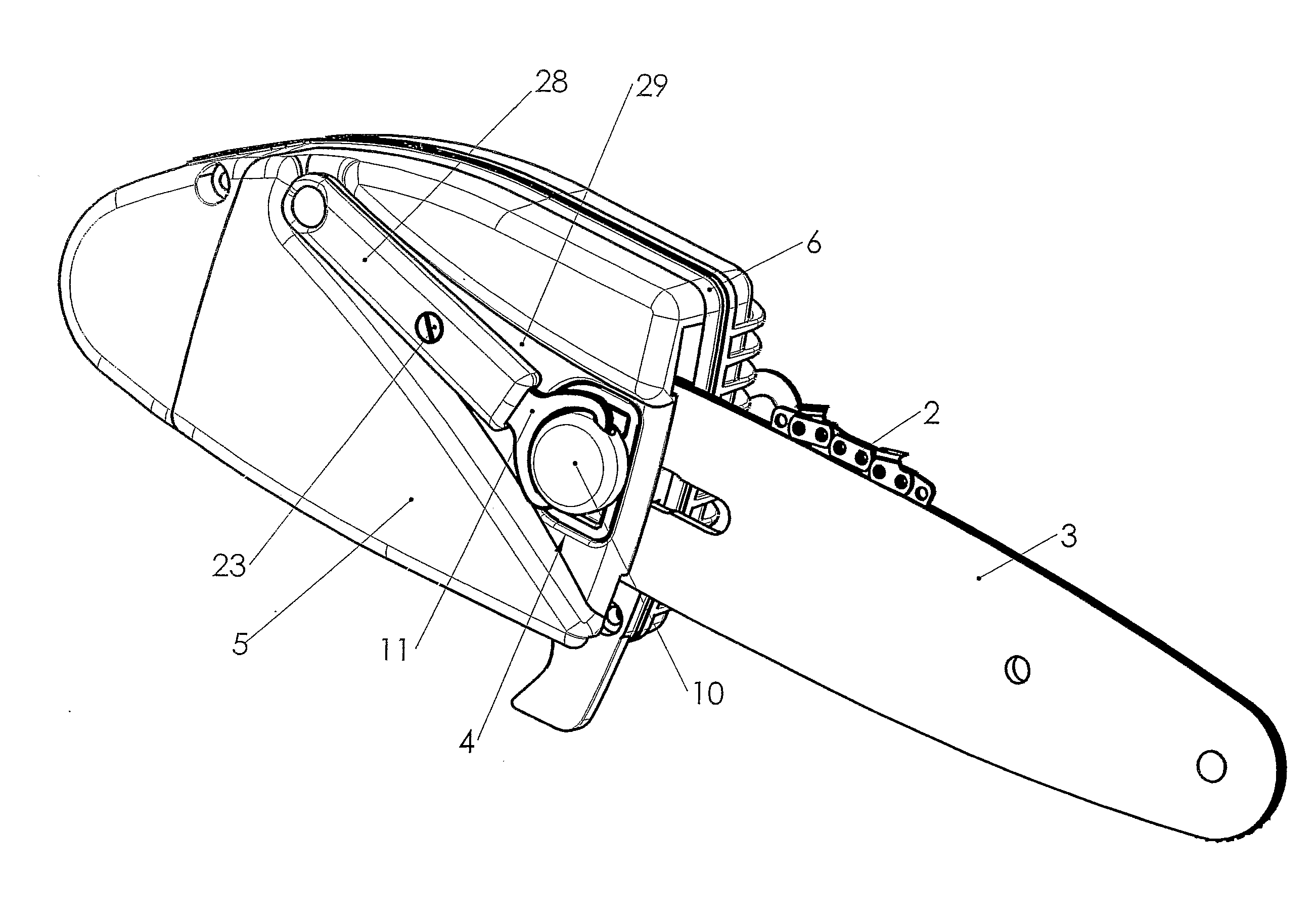
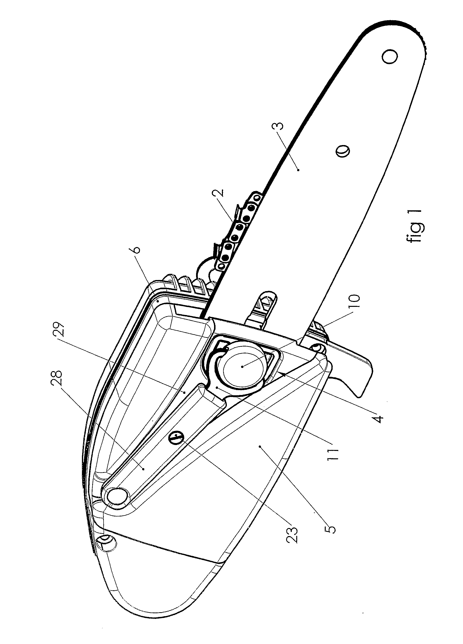
[0049]FIG. 1 shows a portable chain saw 1, which features a partially illustrated cutting chain 2 and a guide bar 3, which maintains and supports this chain 2. A tightening device 4, designated in its assembly by the reference 4 in FIG. 1, tightens this guide bar 3 and a protective housing 5 between a jaw 5A and an assembly body 6.

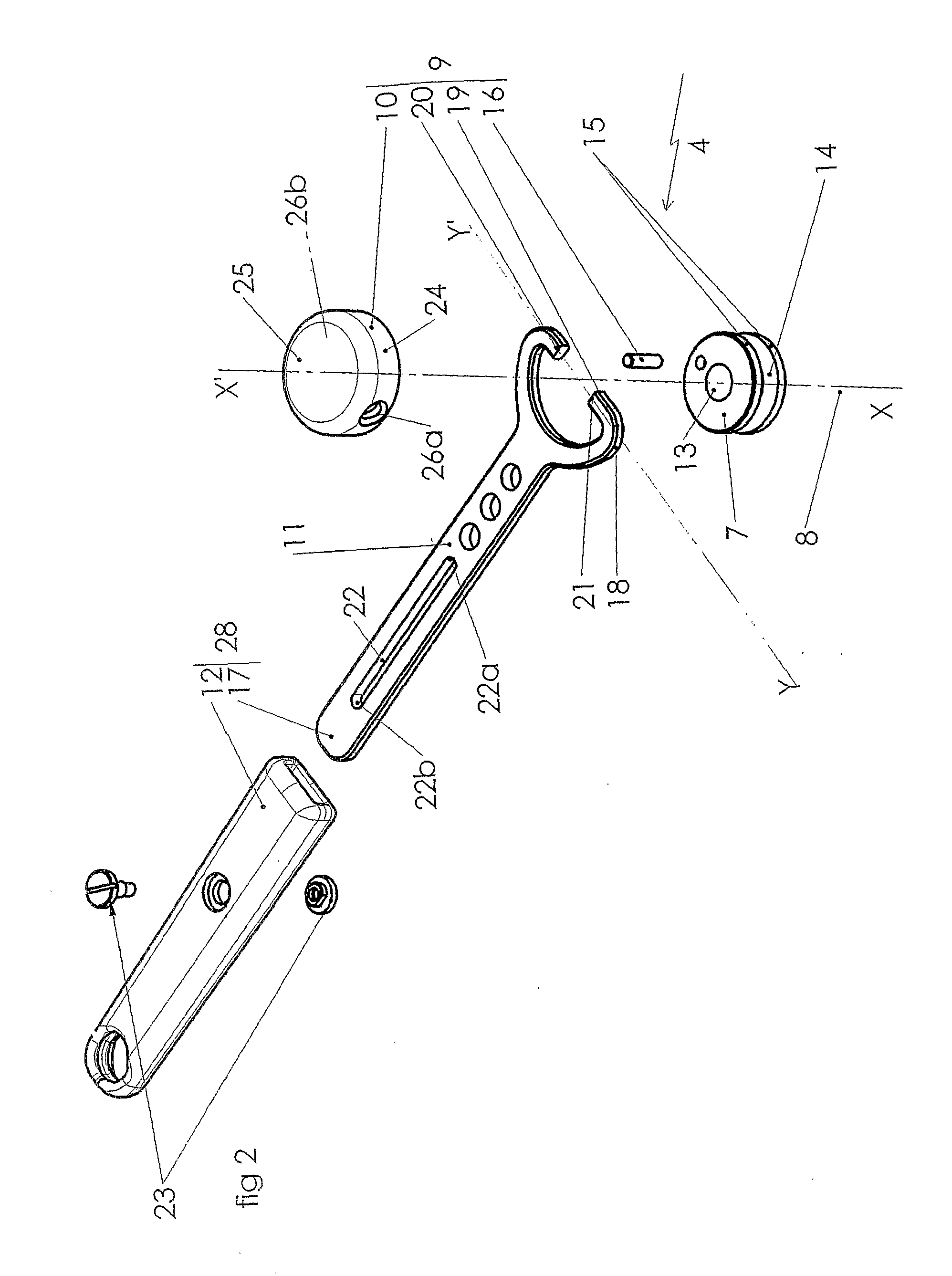
[0050]FIG. 2 shows the tightening device 4, which includes a nut 7 intended to be screwed on a threaded shank 8, for example constituted by the threaded shank of a screw. This tightening device also in...


PUM

PropertyMeasurementUnit
Angleaaaaaaaaaa
Angleaaaaaaaaaa
Areaaaaaaaaaaa

Abstract

Tightening device of the screw-nut type includes a tightening member, which can be rotated, and a rotary wrench for this tightening member, equipped with a handling arm. The wrench and the tightening member are joined by a connecting device in such a way that the wrench can swivel in relation to the tightening member around a swivel axis substantially perpendicular to the screwing axis of the tightening member. Thus, it can be placed in a rest position substantially perpendicular to the screwing axis and can rotate the tightening member around the screwing axis or rotated freely in relation to the tightening member around the screwing axis, over a range of angular clearance (a) of at least 170°.

Description

CROSS-REFERENCE TO RELATED U.S. APPLICATIONS[0001]Not applicable.STATEMENT REGARDING FEDERALLY SPONSORED RESEARCH OR DEVELOPMENT[0002]Not applicable.NAMES OF PARTIES TO A JOINT RESEARCH AGREEMENT[0003]Not applicable.REFERENCE TO AN APPENDIX SUBMITTED ON COMPACT DISC[0004]Not applicable.BACKGROUND OF THE INVENTION[0005]1. Field of the Invention[0006]The present invention concerns a tightening device with a swiveling arm. It also deals with the equipment provided with this tightening device, for example portable tools, and in particular portable chain saws.[0007]2. Description of Related Art Including Information Disclosed Under 37 CFR 1.97 and 37 CFR 1.98[0008]It is common to use a screw or a nut screwed on a threaded rod to obtain a tight grip between two parts. A part mounted by means of a screw-nut system presents the advantage of being removable. However, its disassembly and subsequent reassembly require the loosening of the nuts or the screws by means of an independent tool such...

Claims


Application Information

Patent Timeline
IPC IPC(8): B27B17/14B25B13/48B25B13/08
CPCB27B17/14B25B13/48B25B13/08B27B17/00
Inventor PELLENC, ROGER
Owner PELLENC SA
Learn More