System for recovering waste heat

a waste heat and waste heat technology, applied in the field of power generation, can solve the problems of large amounts of waste heat simply being dumped into the surroundings, reducing the efficiency of conventional heat recovery systems, and emitted oxides and particulates

Inactive Publication Date: 2010-06-17
GENERAL ELECTRIC CO
View PDF13 Cites 63 Cited by
  • Summary
  • Abstract
  • Description
  • Claims
  • Application Information

AI Technical Summary

Problems solved by technology

When waste heat is low grade, such as waste heat having a temperature of heat below 400 degrees Fahrenheit, for example, conventional heat recovery systems do not operate with sufficient efficiency to make recovery of energy cost-effective.
The net result is that vast quantities of waste heat are simply dumped into the surroundings.
However, atmospheric emissions such as nitrogen oxides and particulates may be emitted.
Since the two-cycle systems are more complex and require more components, the overall cost of the two-cycle system is significantly higher.
A cascaded organic rankine cycle system converts surplus heat into electricity within certain temperature ranges but does not recover waste heat over a wide temperature range.
Another disadvantage is the requirement of two separate expander / generator units in each cycle, which increases complexity of the overall system.

Method used


Image

  • System for recovering waste heat
  • System for recovering waste heat
  • System for recovering waste heat

Examples


Embodiment Construction

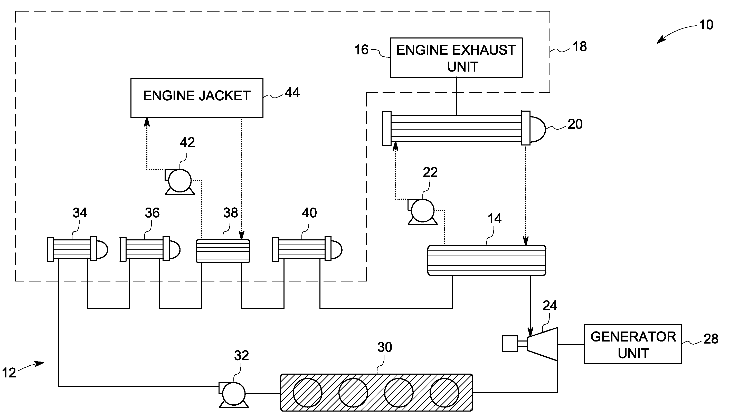
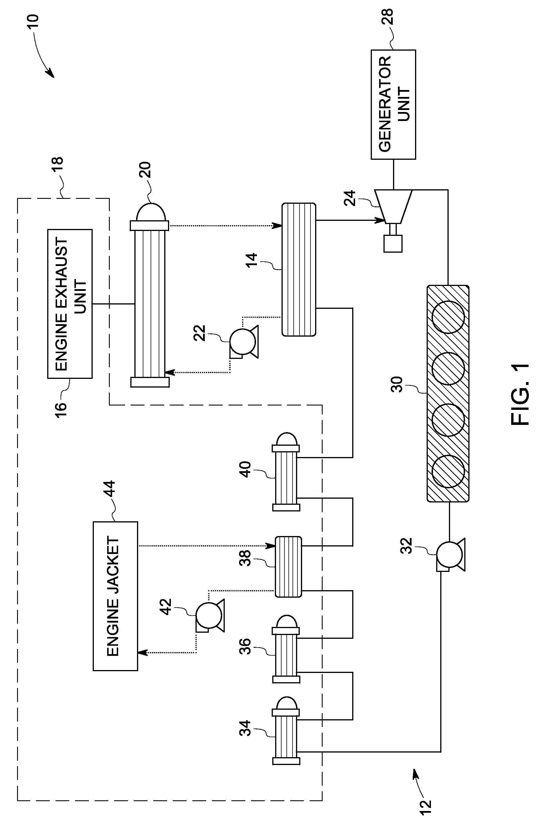
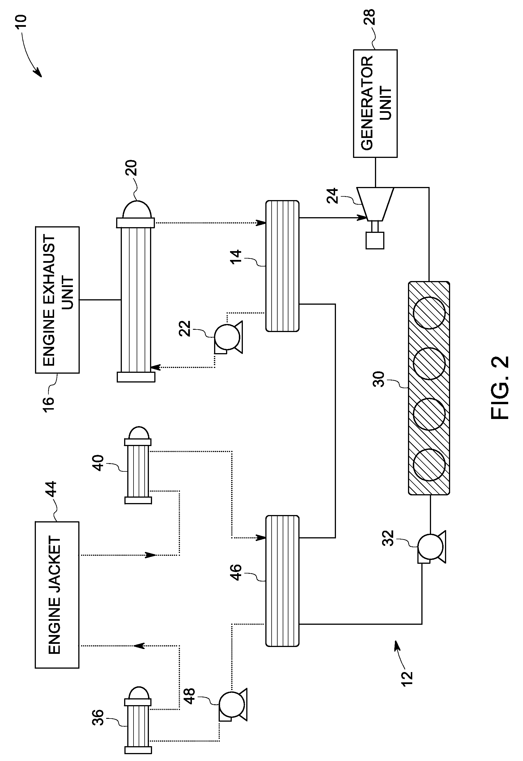
[0016]As discussed in detail below, embodiments of the present invention provide a waste heat recovery system having a heat generation system and one rankine cycle system. The heat generation system includes at least two separate heat sources having different temperatures. The rankine cycle system is coupled to at least two separate heat sources and configured to circulate a working fluid. The rankine cycle system is coupled to at least one heat source among the at least two separate heat sources and configured to remove heat from the at least one heat source to partially vaporize or preheat the working fluid before completely vaporizing or superheating the working fluid. The rankine cycle system is also coupled to another heat source among the at least two separate heat sources and configured to remove heat from the other heat source to completely vaporize or superheat the working fluid. In accordance with the exemplary embodiments of the present invention, the waste heat recovery ...


PUM


Abstract

A waste heat recovery system includes a heat generation system including at least two separate heat sources having different temperatures. A rankine cycle system is coupled to the at least two separate heat sources and configured to circulate a working fluid. The rankine cycle system is coupled to at least one heat source and another heat source among the at least two separate heat sources. The rankine cycle system is configured to remove heat from the at least one heat source to partially vaporize or preheat the working fluid; and remove heat from the other heat source to vaporize or superheat the working fluid.

Description

BACKGROUND[0001]The embodiments disclosed herein relate generally to the field of power generation and, more particularly, to a system for recovering waste heat from a plurality of heat sources having different temperatures for generation of electricity.[0002]Enormous amounts of waste heat are generated by a wide variety of industrial and commercial processes and operations. Example sources of waste heat include heat from space heating assemblies, steam boilers, engines, and cooling systems. When waste heat is low grade, such as waste heat having a temperature of heat below 400 degrees Fahrenheit, for example, conventional heat recovery systems do not operate with sufficient efficiency to make recovery of energy cost-effective. The net result is that vast quantities of waste heat are simply dumped into the surroundings.[0003]Combustion engines are also used to generate electricity using fuels such as gasoline, natural gas, biogas, plant oil, and diesel fuel. However, atmospheric emi...

Claims


Application Information

Patent Timeline
Patent Type & Authority Applications(United States)
IPC IPC(8): F01K25/00F01K23/10
CPCF01K23/065F01K27/02F01K25/08F01K23/10
Inventor AST, GABORBARTLETT, MICHAEL ADAMFREY, THOMAS JOHANNES
Owner GENERAL ELECTRIC CO
Why Eureka
Try Eureka