Switch for a powered pallet conveyor

a technology of powered pallet conveyor and switch, which is applied in the direction of carriages, rail tracks, wagons/vans, etc., can solve the problems of reducing the maximum speed at which the powered pallet conveyor can fulfill the conveying task, and affecting the operation of the switch. , to achieve the effect of reducing space requirements, avoiding high maintenance costs, and reducing wear

Active Publication Date: 2010-06-17
ROFA INDAL AUTOMATION
View PDF16 Cites 65 Cited by
  • Summary
  • Abstract
  • Description
  • Claims
  • Application Information

AI Technical Summary

Benefits of technology

[0010]It is the problem of the present invention to provide a switch for a rail system for a powered pallet conveyor which has no effect on the conveying speed, because the vehicle can travel continuously across the switch without stopping in between, whereby the switching means has reduced space requirements and can be positioned independently from the position and the speed of the vehicle, so that wear is reduced and high maintenance costs are avoided.

Problems solved by technology

This process requires that the vehicle stops on the switch during the positioning process, such that the positioning of the switch delays the transport process.
Both switches are unsatisfactory in so far as the vehicle cannot travel continuously across the switching means without stopping in between.
As a consequence the employment of a conventional switch results in a limitation of the maximum speed which the powered pallet conveyor can fulfill a conveying task.
The limitations imposed by the switch increase in proportion to the number of switches employed in the pathway.
Furthermore, conventional switching means have considerable space requirements.
Moreover, vehicles which are subjected to frequent acceleration / deceleration suffer from increased wear, so that high maintenance costs occur.

Method used


Image

  • Switch for a powered pallet conveyor
  • Switch for a powered pallet conveyor
  • Switch for a powered pallet conveyor

Examples


Embodiment Construction

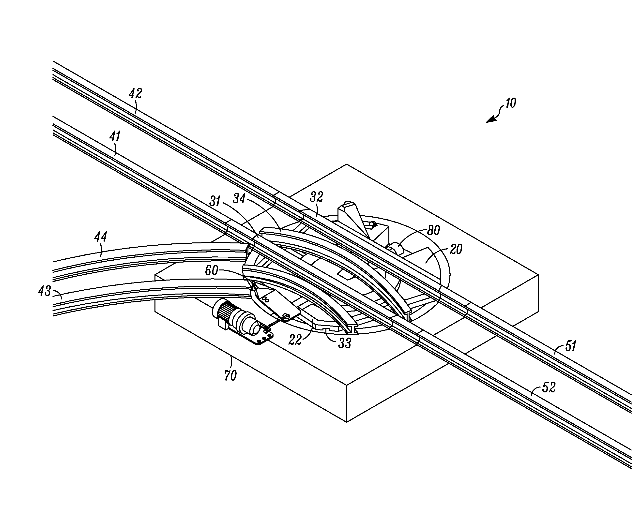
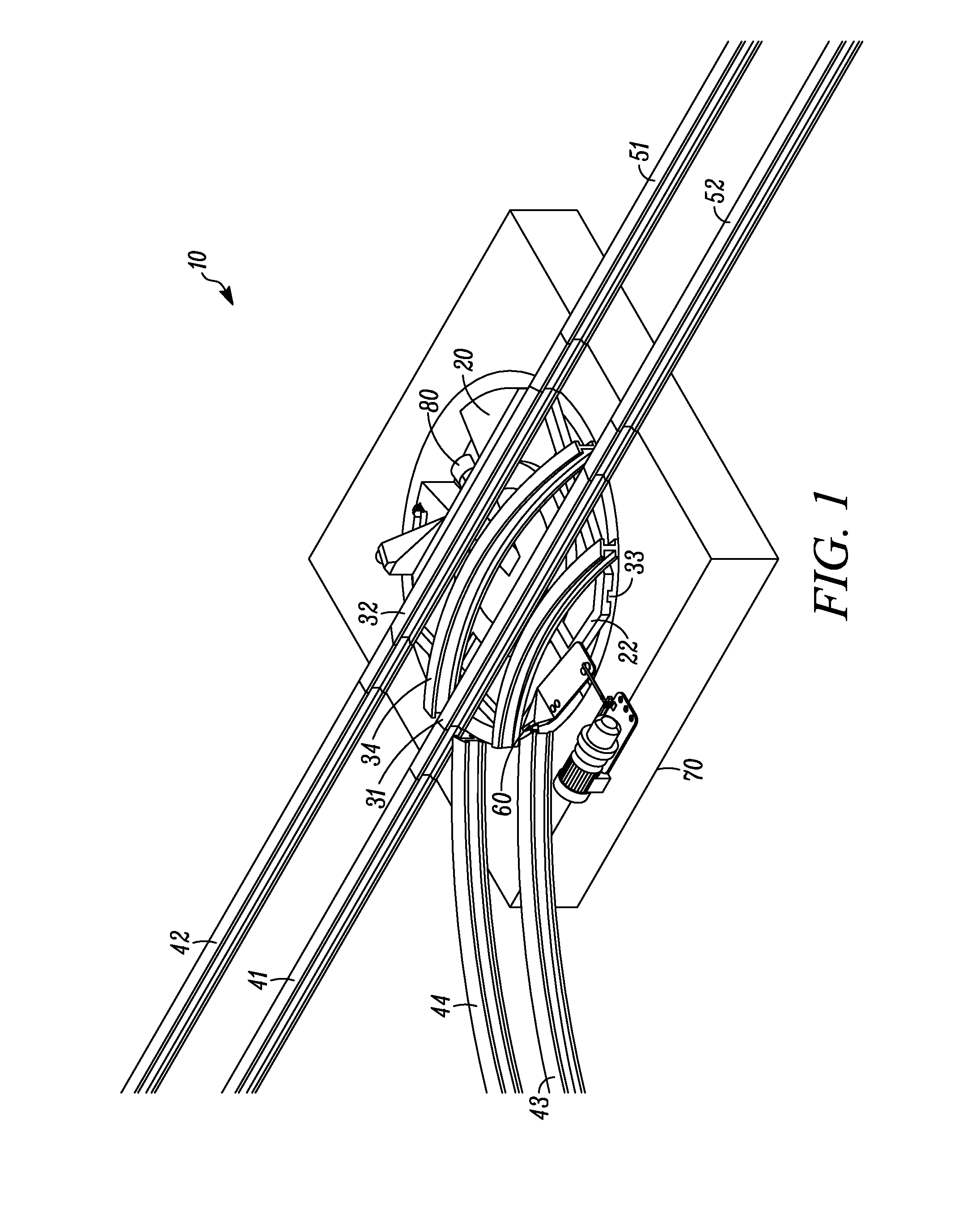
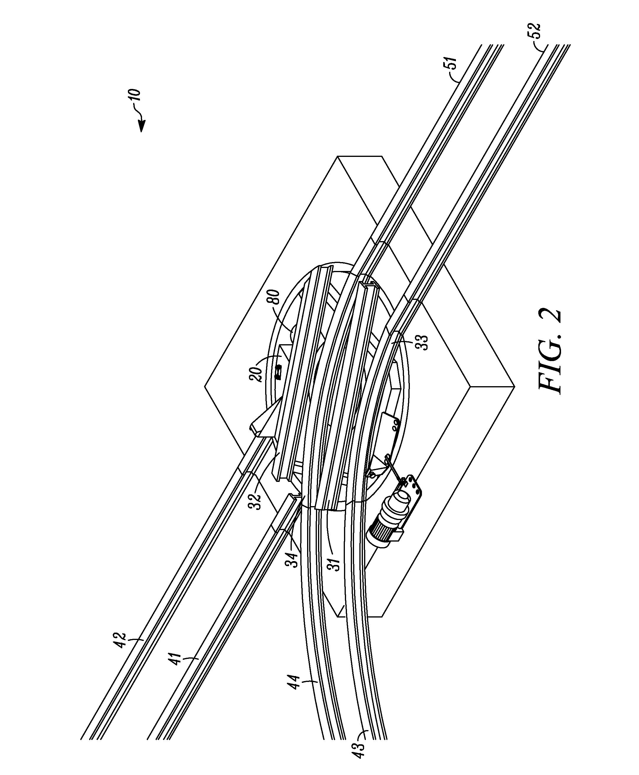
[0027]According to the invention the switch for a powered pallet conveyor comprises a turntable as well as rail portions, which are arranged on the turntable and define a minimum of two travel pathways. Preferably, a travel pathway comprises two parallel rails upon which a vehicle is guided. Such a rail guide is a linear system by which one or more guided wagons run upon a pair of rails and lead to a translation of movement. The track gauge of the travel pathway preferably lies in the range of from 400 to 1500 mm, in particular in the range of from 500 to 1000 mm and more preferably at most 800 mm.

[0028]The turntable is arranged in a rail system in such a way, that rotation of the turntable can bring at least one travel pathway arranged on the turntable into a position in which the rail portions provided on the turntable allow a translation of movement of a guided wagon from a stationary rail inlet across the switch to a stationary rail outlet, wherein the translation of movement is...


PUM


Abstract

In one embodiment of the present disclosure, a switch for a powered pallet conveyor is provided. The switch comprising (a) a turntable and (b) rail portions which are arranged upon the turntable and define at least a first travel pathway and a second travel pathway, whereby the first travel pathway is defined by straight rail portions and a second travel pathway is defined by curved rail portions, so that the central line of the first travel pathway and the departure lines of the second travel pathway respectively pass through the fulcrum of the turntable.

Description

RELATED APPLICATION[0001]This application claims priority to German Patent Application Number DE 20 2008 016 678.0, filed on Dec. 17, 2008, the contents of which are incorporated by reference herein in its entirety.[0002]The present invention relates to a switch for a powered pallet conveyor. Moreover, the present invention relates to a rail system for a powered pallet conveyor, which comprises a switch according to the invention, as well as a conveying system which comprises the rail system and at least one vehicle of a powered pallet conveyor. Lastly, the present invention relates to a special pallet store, which comprises a switch according to the present invention. A switch according to the present invention has the advantage that conveyance can be considerably accelerated, because the positioning of the switch is independent from the position of the conveying vehicle in the rail system.BACKGROUND TO THE INVENTION[0003]Powered pallet conveyors are known and are conventionally ut...

Claims


Application Information

Patent Timeline
Patent Type & Authority Applications(United States)
IPC IPC(8): B61B1/00E01B7/00B61D3/16B61B13/00
CPCB61J1/02E01B23/06E01B7/28B65G47/648B61B13/00B65G63/00E01B7/00E01B25/26
Inventor WEISSBRODT, ANDREAS
Owner ROFA INDAL AUTOMATION
Why Eureka
Try Eureka