
Gasoline engine

a gasoline engine and gasoline technology, applied in the direction of machines/engines, mechanical equipment, electric control, etc., can solve the problems of unburned fuel (hc), inability to optimally set the ignition timing of the second fan-spray injector in the compression stroke, and the system cannot always form a mixture with an optimal distribution, etc., to achieve the effect of reducing hc, increasing exhaust temperature, and long evaporation time of fuel

Inactive Publication Date: 2010-06-17
HITACHI LTD
View PDF10 Cites 17 Cited by
  • Summary
  • Abstract
  • Description
  • Claims
  • Application Information

AI Technical Summary

Benefits of technology

[0016]If an spray angle is increased to increase the utilization of air close to the wall surface, spray colliding with the cylinder wall increases to increase soot, that is, deteriorate emissions such as HC and the like, which poses a problem of causing the lowering of output power.
[0037]In addition, the mixture formation is optimized to ensure a sufficient amount of ignition retard immediately after start-up, which increases exhaust temperature to accelerate activation of a catalyst, thereby reducing HC, and to ensure the elongate evaporation time of fuel to reduce soot.

Problems solved by technology

Therefore, the system cannot always form mixture with an optimum distribution.
For example, if the start-up ignition retard combustion mentioned above is performed, ignition timing for the second fan-spray injector cannot always optimally be set in the compression stroke.
Consequently, fuel may remain on the piston to cause unburned fuel (HC), soot, and the like in some cases.
In addition, mixture cannot always optimally be formed at the place of the ignition plug; therefore, extra fuel is required and combustion tends to become unstable, which poses a problem in that a sufficient amount of ignition retard cannot be ensured.
Because of this, since ignition timing must be set on the advance angle side relative to the plan, afterburning cannot sufficiently be performed.
This poses a problem in that soot (particulate matter) resulting from the diffusive combustion of unburned fuel cannot sufficiently be reduced.

Method used


Image

  • Gasoline engine
  • Gasoline engine
  • Gasoline engine

Examples


Embodiment Construction

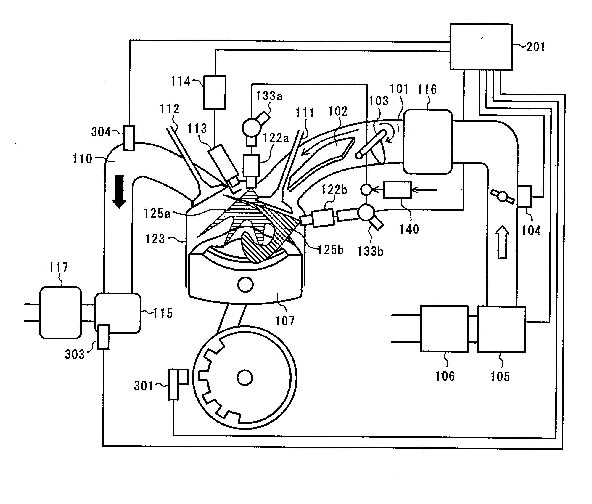
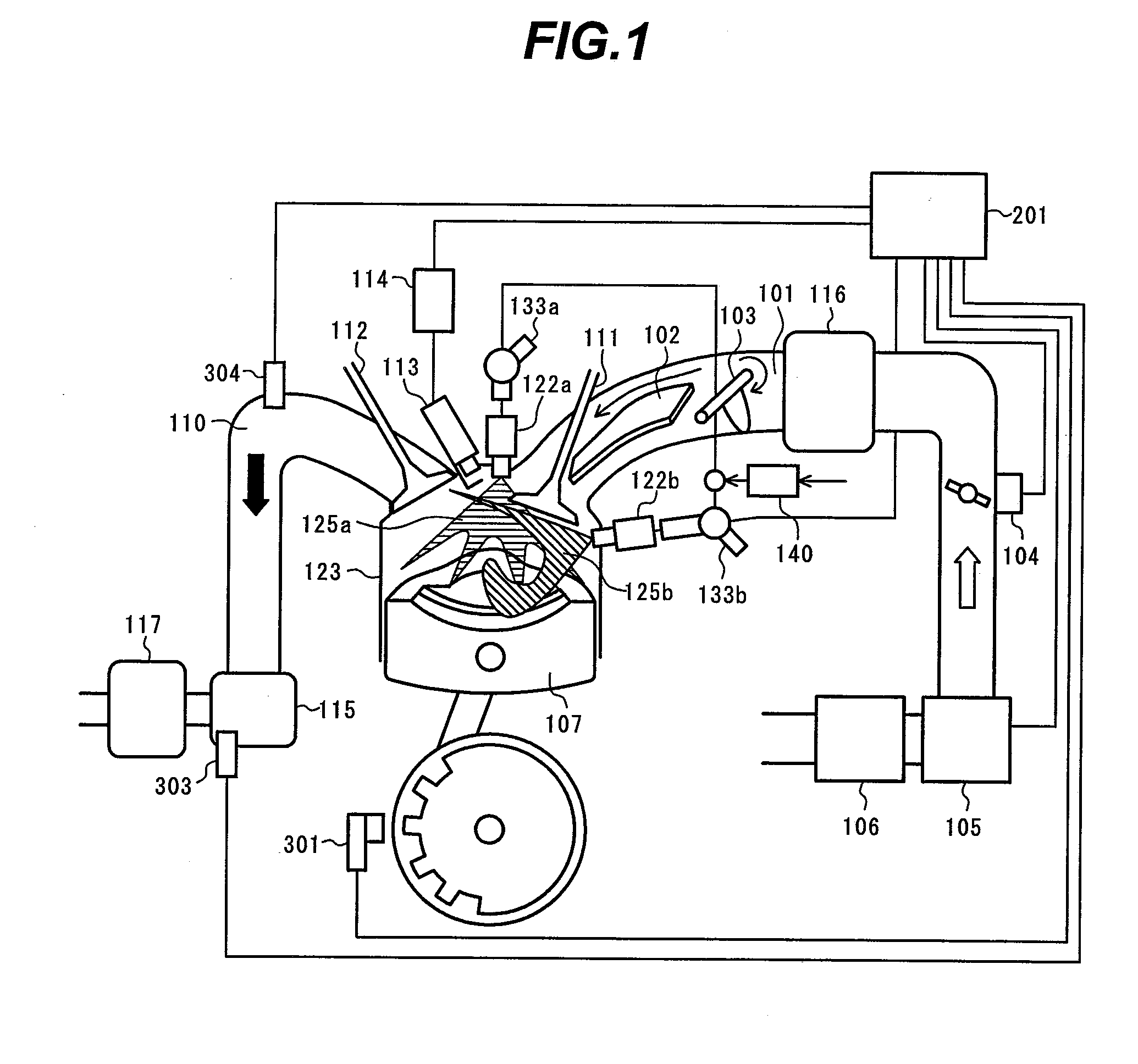
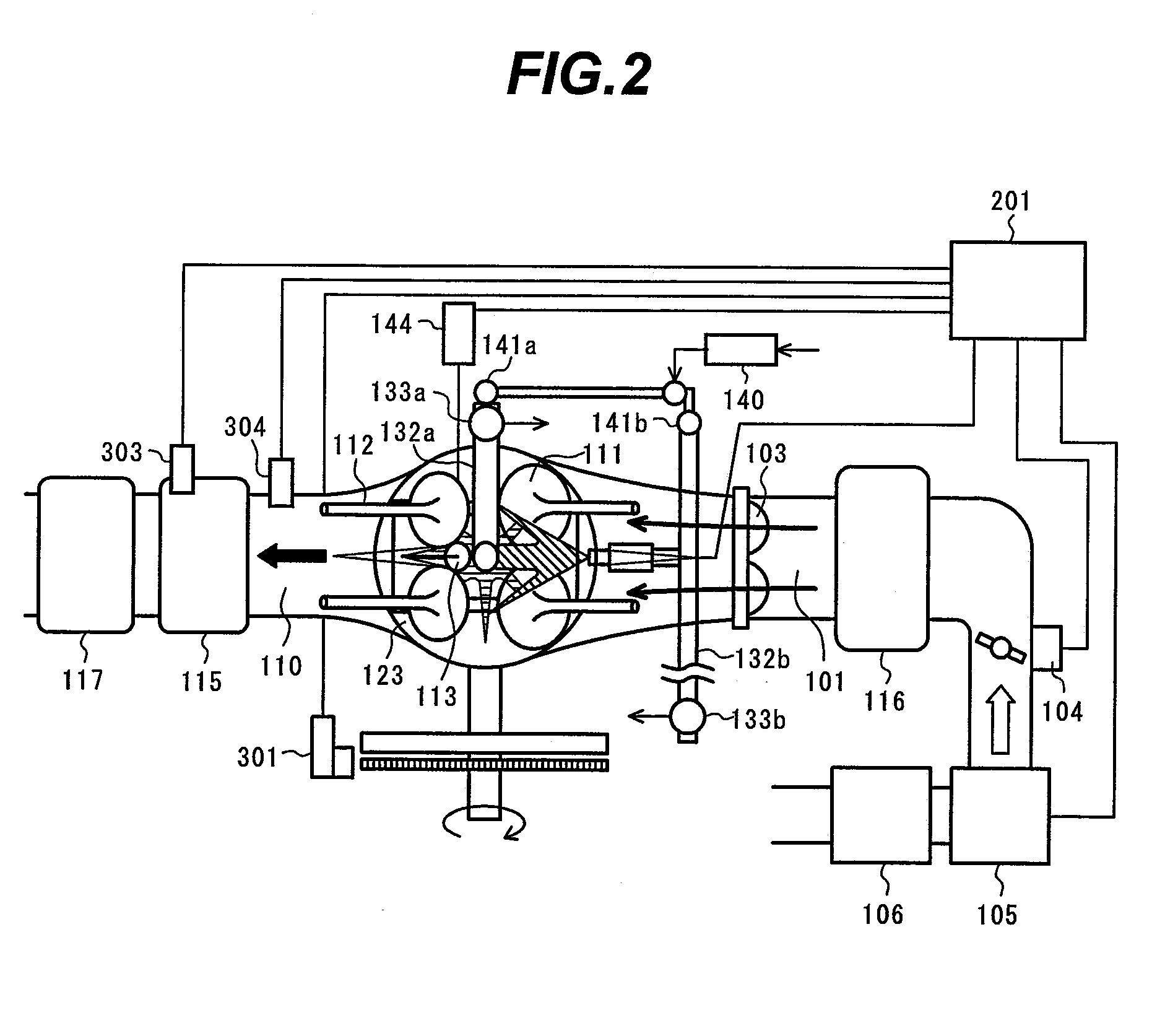
[0072]Configurations of gasoline engines according to embodiments of the present invention will hereinafter be described with reference to FIGS. 1 through 34.

[0073]A description is first given of a configuration of a gasoline engine system according to the present embodiment with reference to FIGS. 1 and 2.

[0074]FIGS. 1 and 2 are system configuration diagrams of the gasoline engine according to the embodiment of the invention. FIG. 1 illustrates an intake system and an exhaust system as viewed from the general side and FIG. 2 as viewed from above of the engine. It is to be noted that while the embodiment mainly assumes a multi-cylinder engine, one cylinder is described with subsequent views for simplicity.

[0075]In FIGS. 1 and 2, an intake pipe 101 is divided into upper and lower portions by a partition plate 102 in an interval between an end face of a cylinder 123 and an intake control valve 103. The intake control valve 103 provided in an upstream portion is installed to close a lo...


PUM


Abstract

A gasoline engine is provided that effectively uses two injectors to enhance homogeneity of mixture at the time of high-load for improving output power and to enable stable operation also when stratified or weak stratified combustion is performed.One cylinder is provided with a first injector 122a and a second injector 122b, which directly inject fuel into the cylinder. An ECU 201 uses one or both the injectors to perform fuel injection during one combustion cycle depending on operating conditions.

Description

BACKGROUND OF THE INVENTION[0001]1. Field of the Invention[0002]The present invention relates generally to gasoline engines that directly inject fuel into a cylinder and burn it mainly by ignition, and more specifically, to a gasoline engine provided with twin-injectors.[0003]2. Description of the Related Art[0004]In-cylinder injection type spark ignition gasoline engines (DI-G engines), which directly inject fuel into a cylinder, have widely been known in the art. They can significantly make a total air-fuel ratio lean by subjecting mixture around an ignition plug to stratification, compared with an engine provided with a multi-port injection system (MPi system) which has predominated. This can achieve a reduction in fuel consumption and an improvement in output power resulting from an intake air cooling effect and from improved combustion efficiency.[0005]In addition, the following method is widely known as a technology characterized by the engines of such a type. Fuel is injected...

Claims


Application Information

Patent Timeline
Patent Type & Authority Applications(United States)
IPC IPC(8): F02B17/00
CPCF02B17/00Y02T10/125F02B23/104F02B23/101F02D41/3029F02D41/3094F02M69/046Y02T10/12
Inventor YAMAGUCHI, JUNICHIMATOHARA, SHINYAINOUE, MASAHIKO
Owner HITACHI LTD
Learn More