

Inhaler and inhaler mouthpiece
a technology of inhaler and inhaler, which is applied in the direction of inhalators, medical atomisers, etc., can solve the problems of reducing inhalation efficiency and increasing aerosol loss, and achieve the effect of reducing the exhalation valve in the inhaler mouthpiece and increasing the size of the inhaler
- Summary
- Abstract
- Description
- Claims
- Application Information
AI Technical Summary
Benefits of technology
Problems solved by technology
Method used
Image

Examples
first embodiment
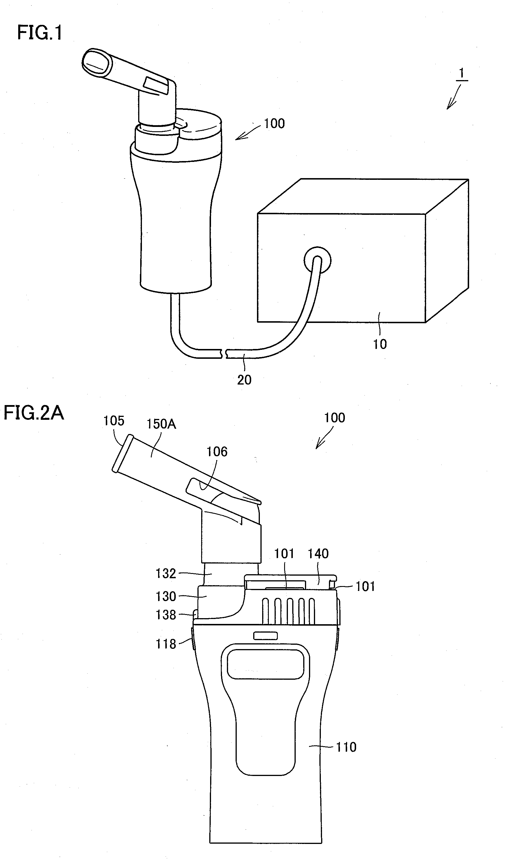
[0080]FIG. 1 is an external view showing an apparatus configuration of an inhaler in a first embodiment of the present invention. As shown in FIG. 1, an inhaler 1 in this embodiment includes a compressor 10, a tube 20, and a nebulizer 100 as an apparatus body. Compressor 10 is connected to nebulizer 100 through tube 20 having flexibility, and compressed air is sent to nebulizer 100 through this tube 20.
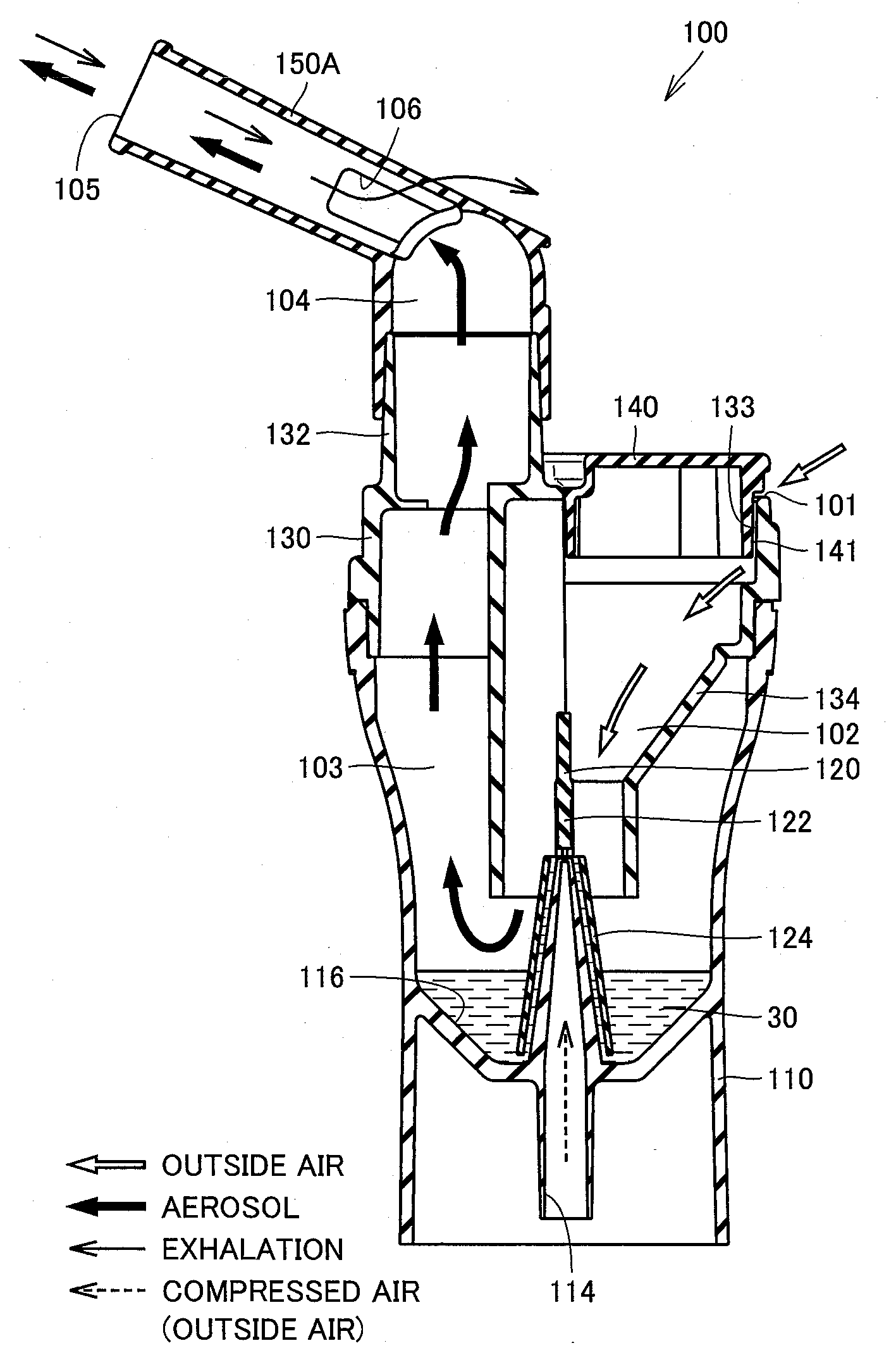
[0081]FIG. 2A and FIG. 2B are views showing the detailed structure of the nebulizer of the inhaler shown in FIG. 1, where FIG. 2A is a side view and FIG. 2B is a front view. FIG. 3 is an exploded perspective view showing a construction structure of the nebulizer shown in FIG. 2A and FIG. 2B. As shown in FIG. 2A, FIG. 2B and FIG. 3, nebulizer 100 includes a case body 110, an atomization portion forming body 120, a flow passage forming body 130, a cap body 140, and a mouthpiece 150A. Among these, case body 110, atomization portion forming body 120, flow passage forming body 130, and cap...
second embodiment
[0113]FIG. 14 is a perspective view of an inhaler mouthpiece in a second embodiment of the present invention. FIG. 15 is an illustration showing an airflow at a time of inhalation in the inhaler mouthpiece in the present embodiment, and FIG. 16 is an illustration showing an airflow at a time of exhalation discharge. In the following, with reference to these figures, a structure of inhaler mouthpiece 150B in the present embodiment and an airflow formed therein will be described. It is noted that inhaler mouthpiece 150B in the present embodiment has a closely analogous structure to that of inhaler mouthpiece 150A in the first embodiment described above, and therefore in the figures the same parts will be denoted with the same reference characters and description thereof will not be repeated here.
[0114]As shown in FIG. 14 and FIG. 15, similar to inhaler mouthpiece 150A in the first embodiment as described above, inhaler mouthpiece 150B in the present embodiment is formed of a tubular m...
third embodiment
[0120]FIG. 17 is a perspective view of an inhaler mouthpiece in a third embodiment of the present invention, and FIG. 18 is a cross-sectional view. FIG. 19 is an illustration showing an airflow at a time of inhalation in the inhaler mouthpiece in the present embodiment, and FIG. 20 is an illustration showing an airflow at a time of exhalation discharge. In the following, with reference to these figures, a structure of inhaler mouthpiece 150C in the present embodiment and an airflow formed therein will be described. It is noted that inhaler mouthpiece 150C in the present embodiment has a closely analogous structure to that of inhaler mouthpiece 150A in the first embodiment described above, and therefore in the figures the same parts will be denoted with the same reference characters and description thereof will not be repeated here.
[0121]As shown in FIG. 17 and FIG. 18, similar to inhaler mouthpiece 150A in the first embodiment as described above, inhaler mouthpiece 150C in the prese...
PUM
 Abstract
Description
Claims
Application Information